MAINTENANCE AND SERVICING
3. Remove screws (A), and remove access c over (B).
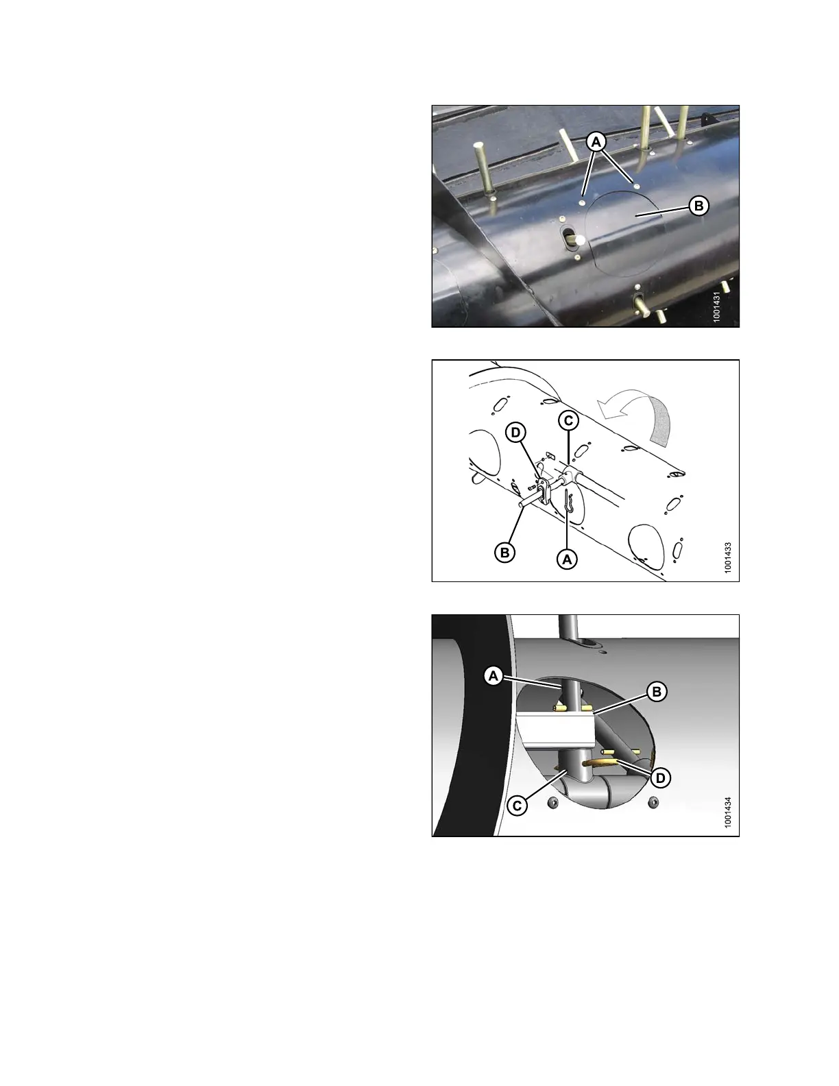
Figure 5.67: Auger
4. From inside the auger, remove hairpin (A), and pull
tine (B) out of bushing (C).
5. From inside the auger, swivel tine away from bushing,
pull from plastic guide (D), and remove from auger.
Figure 5.68: Auger
NOTE:
If the sixth tine (A) opposite drive side is being
replaced, it also must be slipped off drive tube (B).
This particular tine cannot be removed for
normal operation.
6. If tine
is not reinstalled, proceed to next step.
Other
wise, refer to Installing F e e d Auger Tines, page
295.
Figure 5.69: Inside Auger
147695 294 Revision A