OPERATION
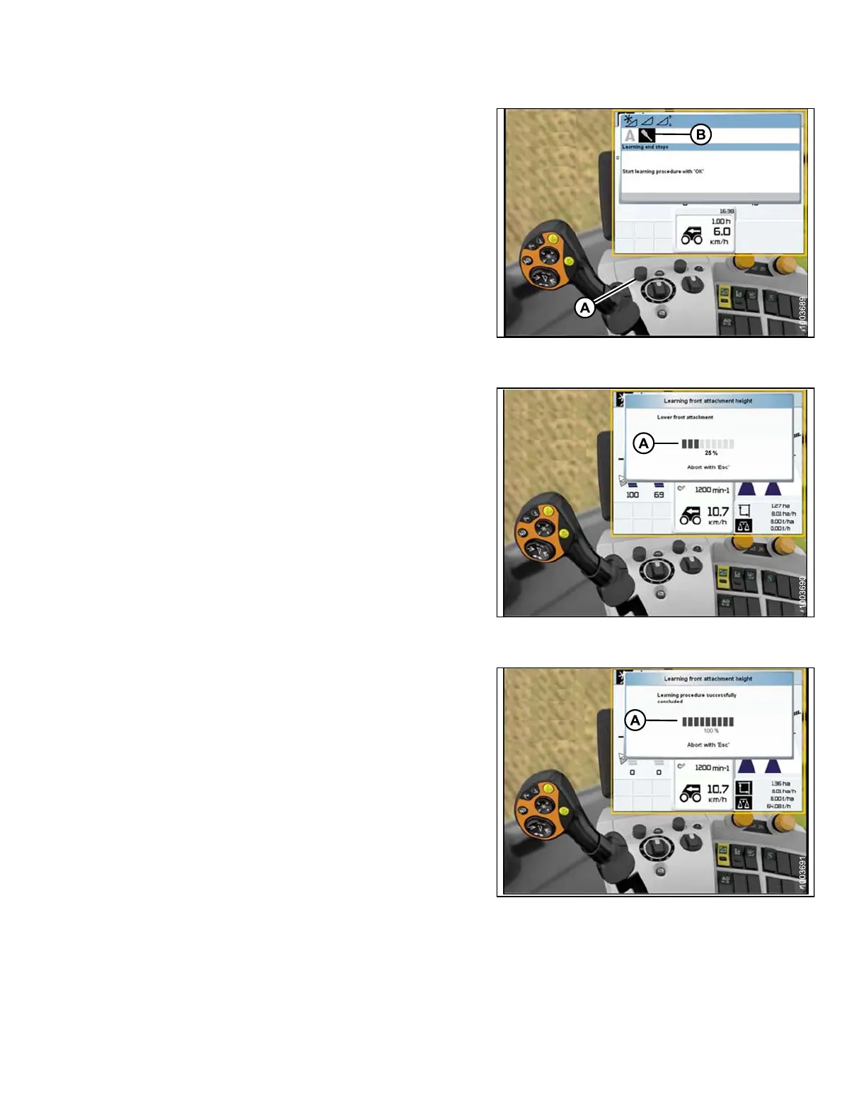
6. Use control knob (A) to highlight the icon that
resembles a screwdriver (B).
7. Engage the combine separator and feeder house.
8. Press control knob (A) and a progress bar chart
will appear.
Figure 3 .233: Combine Display, Console, and
Joystick Lever
9. Fully raise the feeder house and the progress bar chart
will advance to 25% (A).
10. Fully lower the feeder house, and the progress bar
chart will advance to 50%.
11. Fully raise the feeder house and the progress bar chart
will advance t o 75%.
12. Fully lower the feeder house, and the progress bar
chart will advance to 100%.
Figure 3 .234: Combine Display, Console, and
Joystick Lever
13. Ensure the progress bar chart displays 100% (A). The
calibration procedure is now complete.
NOTE:
If the voltage is not within the range of
0.5–4.5 volts at any time throughout the
calibration p r ocess, the monitor will indicate
learning procedure not concluded.
NOTE:
If header float is set too light, an error message
will appear. Back fl oat off three full-turns of the
adjuster bolts to adjust float to approximately
100–125 lbs.
Figure 3 .235: Combine Display, Console, and
Joystick Lever
147695 159 Revision A