OPERATION
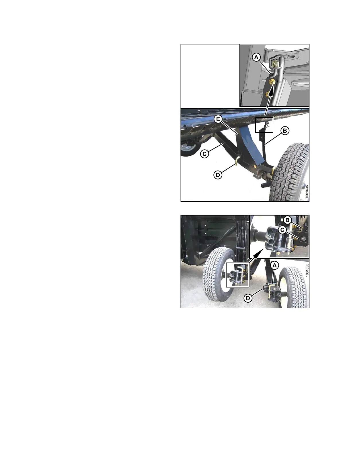
6. Pull pin (A) on brace (B) on the left-hand wheel in front
of the cutterbar. Disengage brace from cutterbar and
lower the brace against axle (C).
7. Remove pin (D), lower the support (E) onto axle, and
reinsert pin into support.
8. Swing axle (C) clockwise towards the rear of
the header.
Figure 3.
279: Right Rear Axle
9. Pull pin (A) at right wheel, swivel w heel
counterclockwise to position shown and lock w ith
pin (A).
10. Remove hairpin (B) from latch (C).
11. Lift wheel, lift latch (C), and engage lug (D) onto left
axle. Ensure latch closes.
12. Secure latch with hairpin (B), with open end of pin
facing rear of combine.
NOTE:
Insta
lling ha irpin with the o pen end facing the
cutte
rbar will cause it to be dislodged by crop
durin
g operation.
IMPO
RTANT:
Chec
k that wheels are locked and that handle is
in lo
cked po sition .
Figur
e 3.280: Rear Axles
147695 186 Revision A