MAINTENANCE AN D SERVICING
NOTE:
For ease of removing or installing knifehead pin,
remove greas e ze rk from pin.
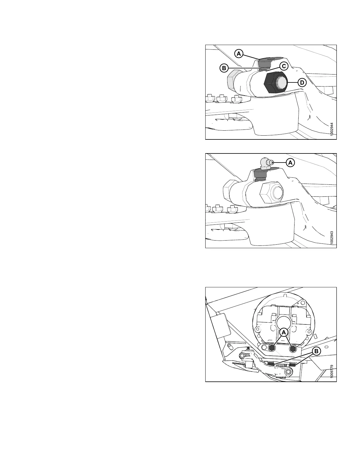
8. Install knife
head pin (A) through the output arm and
into the knife
head.
9. Set groove (B
) in knifehead pin 1/16 in. (1.5 mm)
above (C). In
stall the 5/8 in. x 3 hex head bolt (D) and
nut and torqu
eto160ft·lbf (217 N·m).
Figure 5.116: Knifehead
10. Install grease zerk (A) into the knifehead pin, turn the
grease zerk for easy access.
IMPORTAN T:
Grease knifehead just enough to start a slight
downward movement of knifehead. Over-greasing
will lea d to knife misalignm e nt of the knife which
causes guards to overheat and drive systems
to overload.
Figure 5.117: Knifehead
11. Check the knife drive box pulley and drive pulley
alignment. If adjustment is required, contact your
MacDon Dealer.
12. Tighten knife
drive box side bolts (A) first, then the
bottom bolts (
B). Torque to 200 ft·lbf (271 N·m).
13. Stroke the out
put arm to mid stroke, check and ensure
that the knif
e bar does not contact the front of the
first guard. I
f adjustment is required, contact your
MacDon Deale
r.
14. Install and t
ension the knife drive belt(s). Refer to 5.9.2
Knife Drive
Belts, page 318.
15. Close endsh
ield. Refer to Closing Endshields, page
34.
Figure 5.118: Knife Drive Box
147695 317 Revision A