MAINTENANCE AND SERVICING
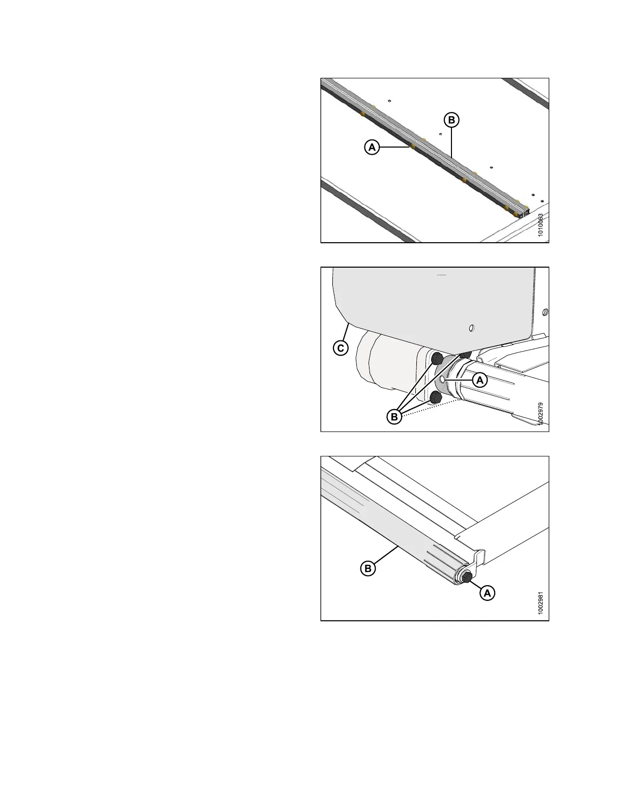
5. Remove fasteners (A) and tube connectors (B) at the
draper joint to uncouple the draper.
6. Pull the draper off the drive roller.
Figure 5.177: Draper Connector
7. Line up the setscrews with the hole (A) in the guard.
Remove the tw o setscrews that hold the m otor onto
the drive ro ller.
NOTE:
The setscrews are a 1/4 turn apart.
8. Remove the four bolts (B) that hold motor to the drive
roller arm.
NOTE:
Plastic shield (C) may require removal to gain access
to the top bolt.
Figure 5.178: Drive Roller
9. Remove bolt (A) that secures the other end of the drive
roller (B) to the support arm.
10. Remove the drive roller (B).
Figure 5.179: Drive Roller
Replacing Side Draper Drive Roller Bearing
1. Rem
ove draper idler roller assembly. Refer to Removing Side Draper Drive Roller, page 343.
147695 344 Revision A