OPERATION
Reposition center arm cylinder as follows:
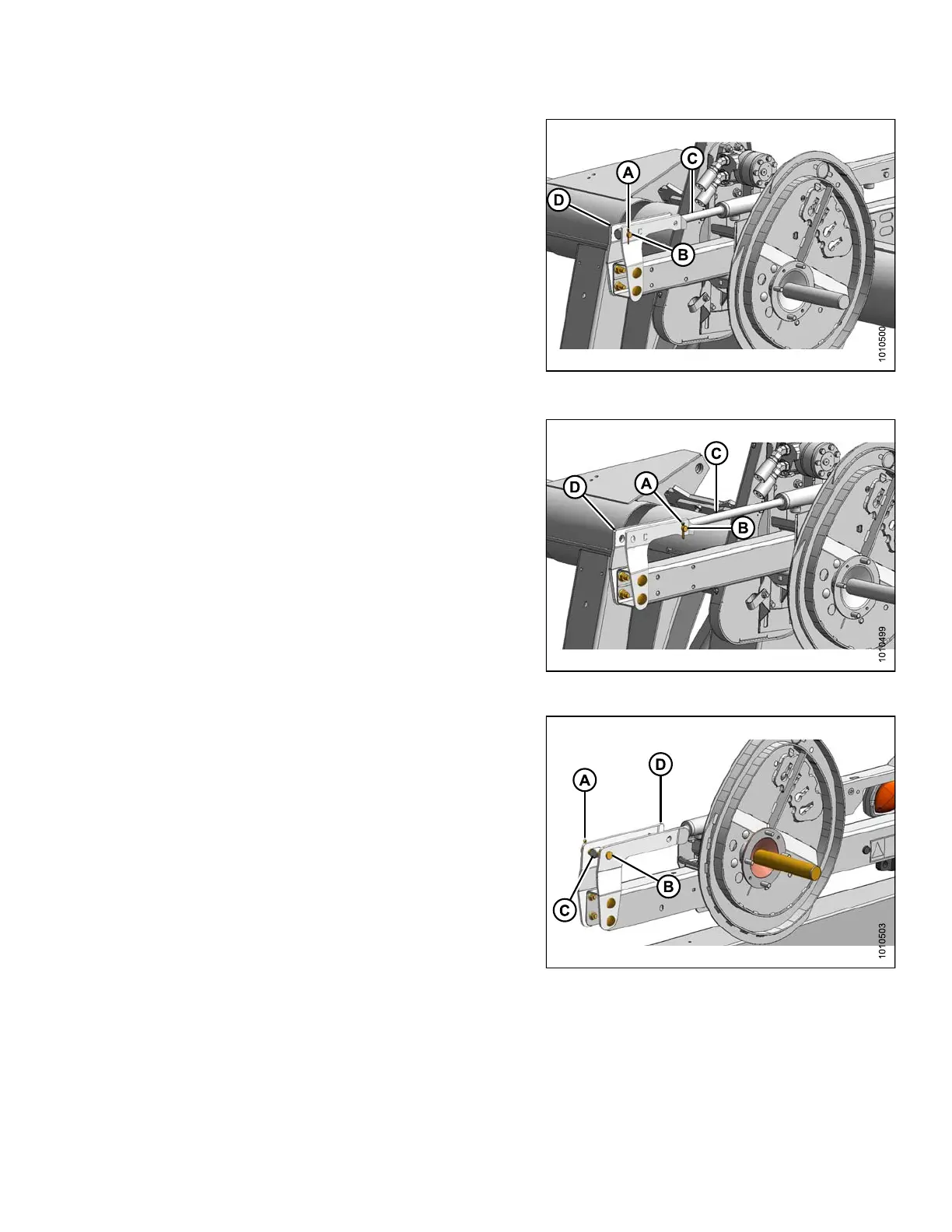
NOTE:
Reel components are not shown for clarity.
6. Remove cotter
pin (A) and remove clevis pin (B).
7. Push reel bac
k until cylinder rod (C) lines up with the
aft hole in br
ackets (D).
8. Reinstall th
e clevis pin (B) at new position and secure
with cotter p
in (A).
Figure 3.72: Forward Position – Center A rm
Figure 3.73: Aft Position – Center Arm
Reposition right arm cylinder as follo ws:
NOTE:
Reel components are not shown for clarity.
9. Remov
e cotter pin (A) and remove clevis pin (B).
10. Push r
eel back until cylinder rod (C) lines up with the
aft ho
le in brackets (D).
11. Rein
stall the clevis pin (B) at new position and secure
with
cotter pin (A).
Figure 3.74: Forward Position – Right Arm
147695 79 Revision A