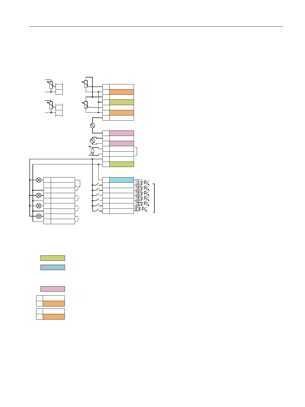
4.2.3 Terminal strips
Terminal strips with wiring example
b9RXWSXWPD[bP$
$QDORJLQSXWb9bbb9bP$bbbP$
$QDORJLQSXWb9bbb9bP$bbbP$
5HIHUHQFHIRUWHUPLQDO
5HIHUHQFHIRUWHUPLQDO
$QDORJRXWSXWb9bಹbb9bP$bಹbbP$
5HIHUHQFHIRUWHUPLQDOVDQG
5HIHUHQFHIRUWHUPLQDOVDQG
5HIHUHQFHIRUWHUPLQDOVDQG
5HIHUHQFHIRUWHUPLQDOVDQG
$QDORJRXWSXWb9bಹbb9bP$bಹbbP$
5HIHUHQFHIRUGLJLWDOLQSXWV
b9RXWSXWPD[bP$
'LJLWDORXWSXWVPD[b$b9b'&b$b9b$&
'LJLWDOLQSXWV
&RQQHFWLRQFRQWDFWVVZLWFKLQJWRSRUPSRWHQWLDO
ORZb9KLJK!b9PD[b9
7HPSHUDWXUHVHQVRU37&.7<3WELPHWDO
$,
$,*1'
$2
9RXW
*1'
$,
$,*1'
9RXW
*1'
',&20
',
',
',
',
',
',
9
H[W
*1'
H[W
9
H[W
*1'
H[W
'212
'2&20
'21&
'2&20
'212
'2&20
'212
'2&20
'212
;
;
;;
ุN˖
ุN˖
702725
702725
$2*1'
$2
$2*1'
1)
The digital outputs are designed for low voltage systems of overvoltage category II. In installations of overvoltage category
III, galvanic isolation is required between the supply network and the digital output.
Figure 4-11 Wiring the digital inputs with p-switching contacts and an internal 24 V power supply (terminal 9)
All terminals with the "GND" reference potential are internally connected with one another.
The reference potential "DI COM" is not internally connected with "GND".
→ If, as shown above, you wish to use the 24 V supply from terminal 9 as supply for the digital
inputs, a jumper is required between terminals 28 and 69.
The reference potential of the analog outputs is not internally connected with "GND".
You may use the internal 10 V power supply or an external power supply to supply the analog
inputs.
→ When you use the internal 10 V power supply, you must connect "AI GND" with "GND".
Additional options for wiring the digital inputs
The following diagram shows how you supply the digital inputs and digital outputs with an
external voltage.
Wiring
4.2 Control interfaces
SINAMICS G120XA converter
Operating Instructions, 03/2019, FW V1.0, A5E44751205B AB 79

 Loading...


