Analog-to-digital converter (ADC) RM0453
576/1450 RM0453 Rev 5
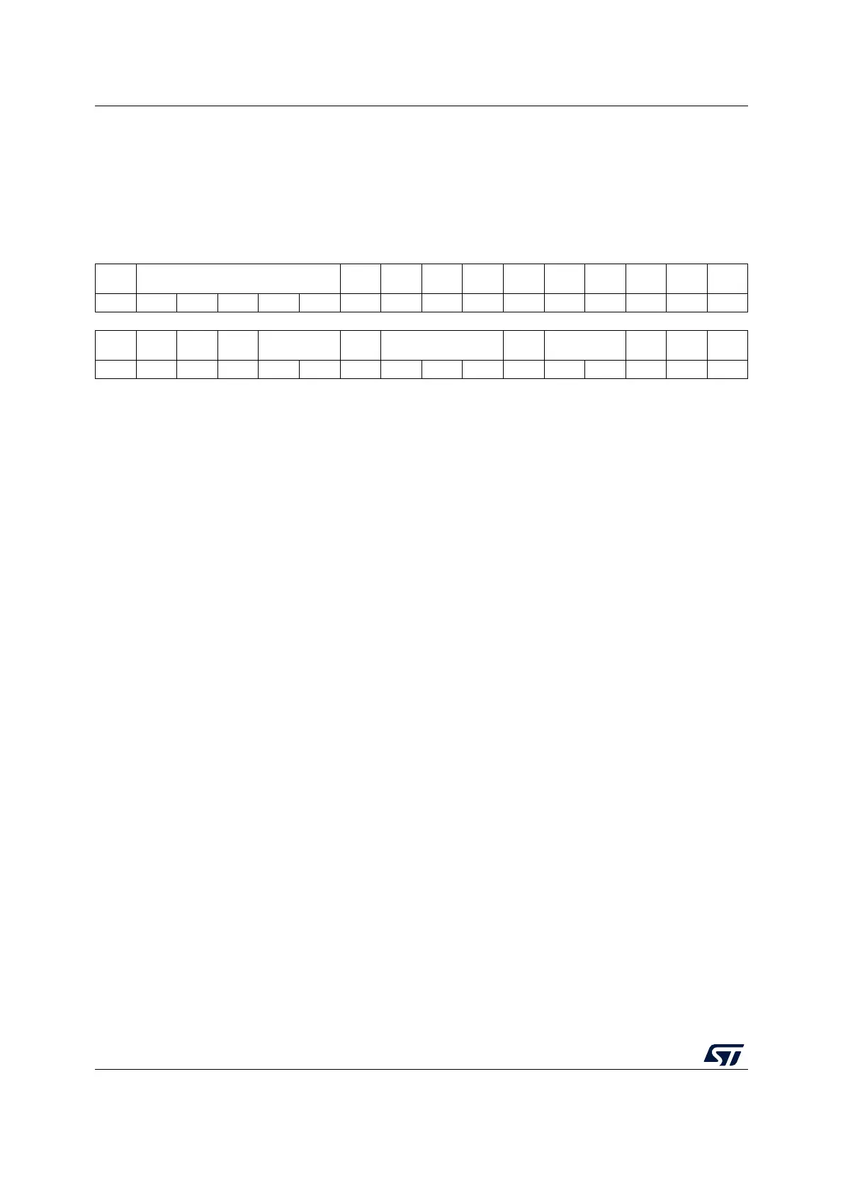
18.12.4 ADC configuration register 1 (ADC_CFGR1)
Address offset: 0x0C
Reset value: 0x0000 0000
The software is allowed to program ADC_CFGR1 only when ADEN is cleared in ADC_CR.
31 30 29 28 27 26 25 24 23 22 21 20 19 18 17 16
Res. AWD1CH[4:0] Res. Res.
AWD1E
N
AWD1S
GL
CHSEL
RMOD
Res. Res. Res. Res.
DISCE
N
rw rw rw rw rw rw rw rw rw
1514131211109876543210
AUTOF
F
WAIT CONT
OVRM
OD
EXTEN[1:0] Res. EXTSEL[2:0] ALIGN RES[1:0]
SCAND
IR
DMAC
FG
DMAE
N
rw rw rw rw rw rw rw rw rw rw rw rw rw rw rw
Bit 31 Reserved, must be kept at reset value.
Bits 30:26 AWD1CH[4:0]: Analog watchdog channel selection
These bits are set and cleared by software. They select the input channel to be guarded by
the analog watchdog.
00000: ADC analog input Channel 0 monitored by AWD
00001: ADC analog input Channel 1 monitored by AWD
.....
10001: ADC analog input Channel 17 monitored by AWD
Others: Reserved
Note: The channel selected by the AWDCH[4:0] bits must be also set into the CHSELR
register.
Bits 25:24 Reserved, must be kept at reset value.
Bit 23 AWD1EN: Analog watchdog enable
This bit is set and cleared by software.
0: Analog watchdog 1 disabled
1: Analog watchdog 1 enabled
Note:
Bit 22 AWD1SGL: Enable the watchdog on a single channel or on all channels
This bit is set and cleared by software to enable the analog watchdog on the channel
identified by the AWDCH[4:0] bits or on all the channels
0: Analog watchdog 1 enabled on all channels
1: Analog watchdog 1 enabled on a single channel
Note:
Bit 21 CHSELRMOD: Mode selection of the ADC_CHSELR register
This bit is set and cleared by software to control the ADC_CHSELR feature:
0: Each bit of the ADC_CHSELR register enables an input
1: ADC_CHSELR register is able to sequence up to 8 channels
Note: If CCRDY is not yet asserted after channel configuration (writing ADC_CHSELR register
or changing CHSELRMOD or SCANDIR), the value written to this bit is ignored.
Bits 20:17 Reserved, must be kept at reset value.