Section 6: Triggering Model 2601B-PULSE System SourceMeter Instrument Reference Manual
6-36 2601B-PULSE-901-01A April 2020
Digital I/O
The 2601B-PULSE has a digital input/output port that can be used to control external digital circuitry.
For example, you can use a handler that is used to perform binning operations with a digital I/O port.
Port configuration
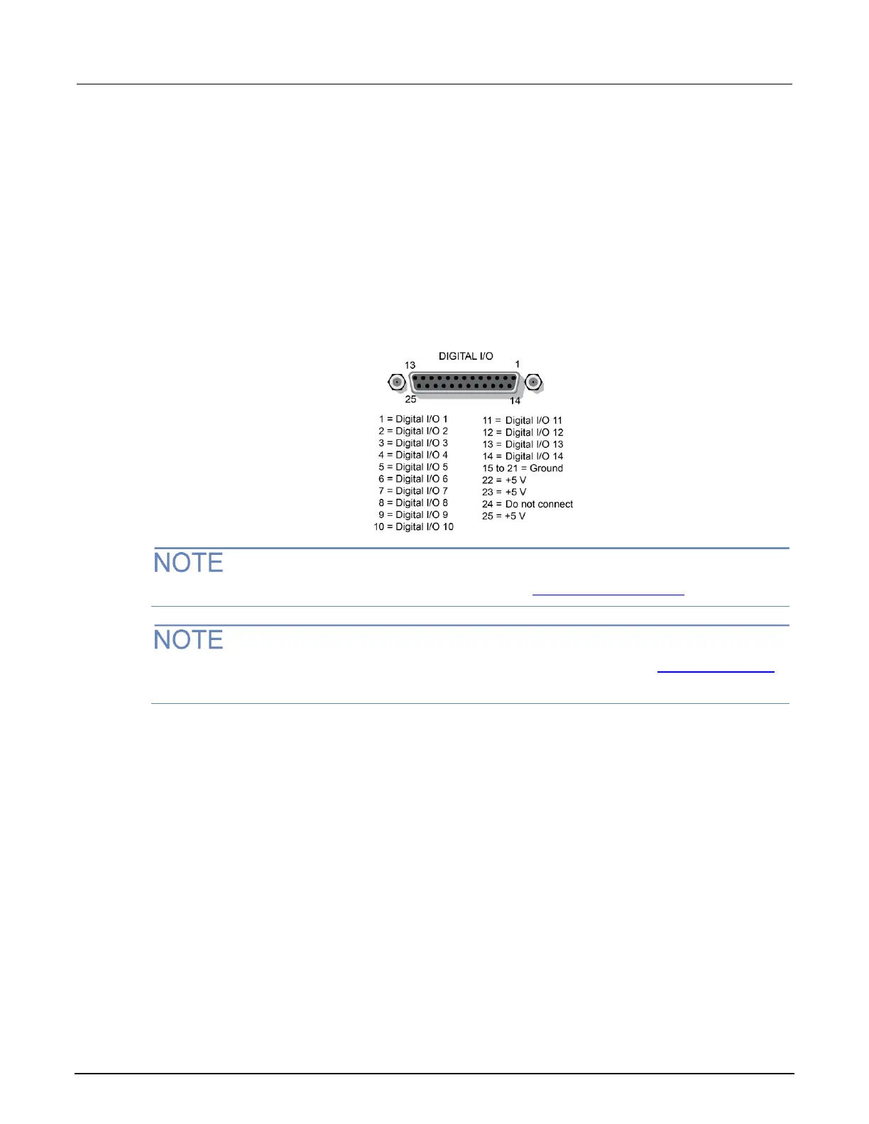
The digital I/O port, a standard female DB-25 connector (shown below), is on the rear panel.
Figure 96: Digital I/O port pin assignments
For a schematic diagram of the digital I/O hardware, refer to Digital I/O configuration. (on page 6-37)
For information on using the digital I/O port as part of an interlock setup, refer to Using the interlock
(on page 2-42).
Connecting cables for Trigger Link
Use a cable equipped with a male DB-25 connector (Keithley Instruments part number CA-126-1A;
L-com part number CSMN25MF-5) to connect the digital I/O port to other Keithley Instruments models
equipped with a Trigger Link (TLINK).
Digital I/O lines
The port provides 14 digital I/O lines. Each output is set high (+5 V) or low (0 V) and can read high or
low logic levels. Each digital I/O line is an open-drain signal.
+5 V output
The digital I/O port provides three +5 V dc output lines that you can use to drive external logic circuitry.
Maximum combined current output for all lines is 250 mA. These lines are protected by a
self-resetting fuse with a one hour recovery time.

 Loading...


