Section 2: Installation Model 2601B-PULSE System SourceMeter Instrument Reference Manual
2-44 2601B-PULSE-901-01A April 2020
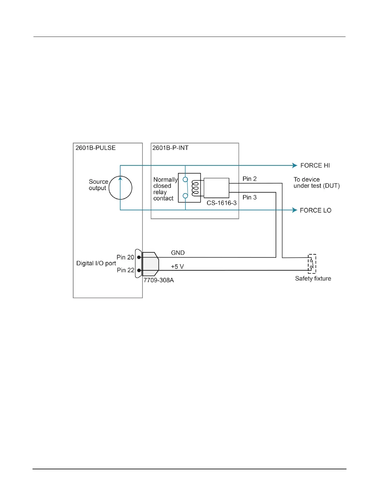
Interlock connections through digital I/O port
The following figure shows digital I/O port pin 20 as ground. You can also use pin 15, 16, 17, 18, 19,
or 21 as ground.
The +5 V source is shown as digital I/O port pin 22. You can also use pin 23 or 25 as the +5 V source.
Use a two-conductor low-voltage cable to connect the +5 V source to the low-voltage remote switch.
The recommended cable is 22 AWG (20 AWG maximum) with 1.2 mm to 1.6 mm outer diameter.
Figure 24: Digital I/O port interlock connections
Interlock connections using external source
Use a +5 V external power supply with a ±5% tolerance. The 2601B-P-INT interlock requires
approximately 125 mA to operate.
Use a two-conductor low-voltage cable to connect the +5 V source to the low-voltage remote switch.
The recommended cable is 22 AWG (20 AWG maximum) with 1.2 mm to 1.6 mm outer diameter.

 Loading...


