Section 4: Sourcing and measuring Model 2601B-PULSE System SourceMeter Instrument Reference Manual
4-8 2601B-PULSE-901-01A April 2020
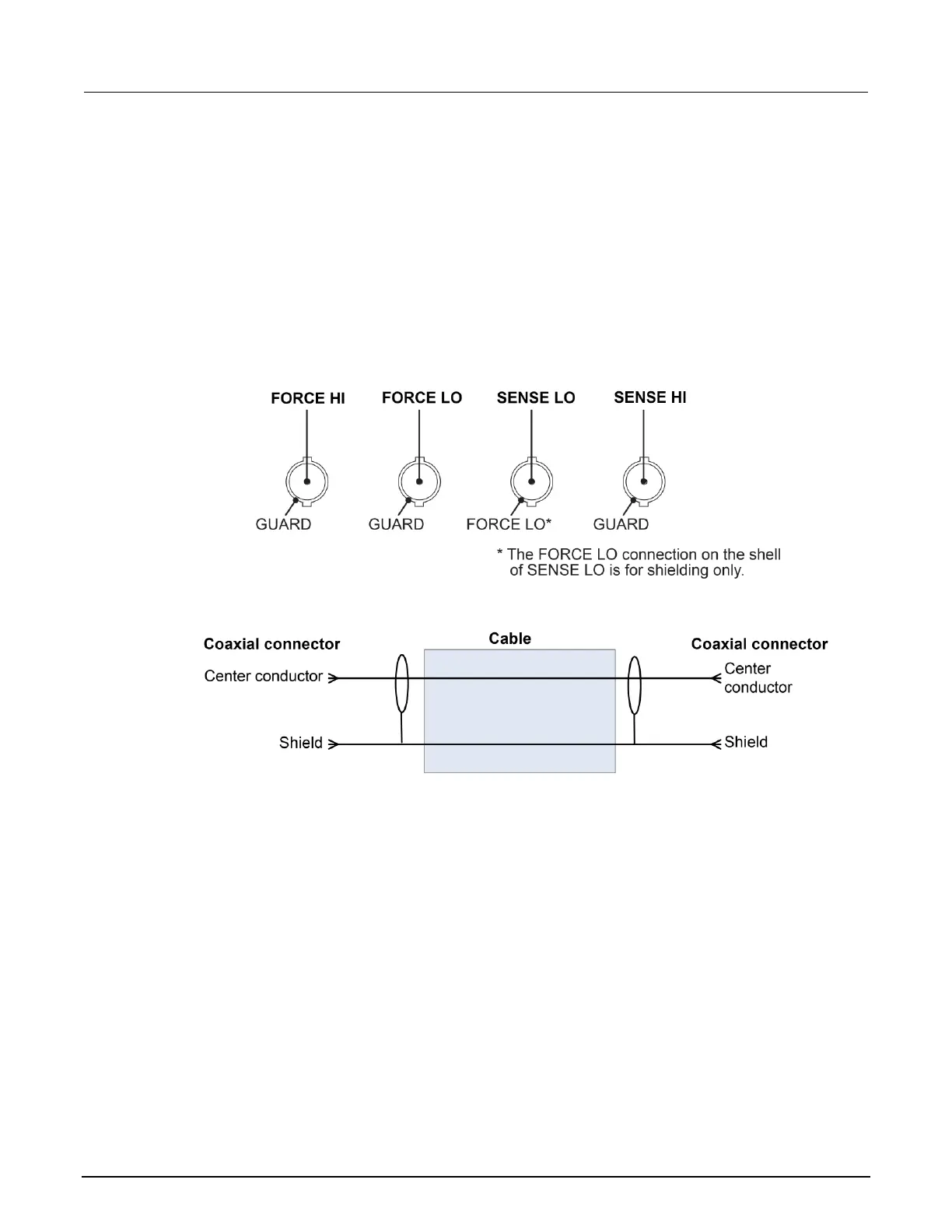
FORCE and SENSE connectors
You make connections from the instrument to the device under test (DUT) using the BNC connections
on the 2601B-P-INT.
The FORCE HI, FORCE LO, and SENSE HI connectors of the 2601B-P-INT have GUARD on the
shell. The SENSE LO connector has FORCE LO on the shell. The FORCE LO shell connection is for
shielding only and should not be used to carry signal; use the center pin of the FORCE LO connector
instead.
Figure 38: 2601B-P-INT FORCE and SENSE shell connections
Figure 39: Coaxial connectors for 2601B-PULSE
All connections are electrically isolated from chassis ground.
The rear panel of the 2601B-PULSE provides a low-noise chassis ground banana jack that can be
used as a common signal ground point for the SENSE and FORCE LOs. This low-noise signal ground
banana jack is connected to the chassis through a frequency variable resistor (FVR). The FVR,
shown in the figure below, is used to isolate the SMU from high frequencies that may be present on
the chassis of the 2601B-PULSE. As frequencies on the chassis increase, the resistance of the FVR
increases to dampen their effects. For dc to 60 Hz, the FVR is a virtual short (zero ohms).

 Loading...


