Model 2601B-PULSE System SourceMeter Instrument Reference Manual Section 3: Instrument description
2601B-PULSE-901-01A April 2020 3-5
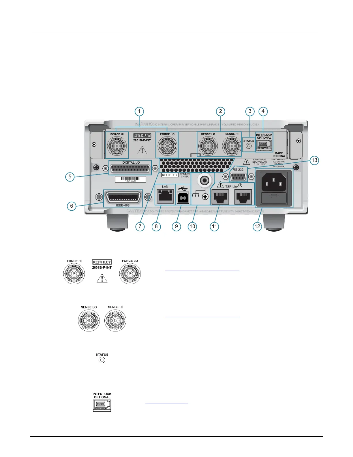
Rear panel
The 2601B-PULSE rear panel with the 2601B-P-INT installed is shown below. The descriptions of the
rear-panel components follow the figure.
Figure 28: Rear panel
1. FORCE HI and FORCE LO connectors
These connectors provide connections for FORCE HI and FORCE LO.
Refer to FORCE and SENSE connectors (on page 4-8) for additional
information.
2. SENSE LO and SENSE HI connectors
These connectors provide connections for SENSE LO and SENSE HI.
Refer to FORCE and SENSE connectors (on page 4-8) for additional
information.
3. STATUS indicator
This LED indicates the status of the interlock. When the interlock is not
asserted, the indicator is off. When the interlock is asserted, the indicator
is on.
4. INTERLOCK connector
This connector provides a connection for the optional interlock. Refer to
Using the interlock (on page 2-42) for information on setting up and
connecting the interlock.

 Loading...


