Model 2601B-PULSE System SourceMeter Instrument Reference Manual Section 7: Theory of operation
2601B-PULSE-901-01A April 2020 7-9
Load considerations for voltage source
The boundaries within which the 2601B-PULSE operates depend on the load of the device-under-test
(DUT) that is connected to the output. The following topics show operation examples for resistive
loads that are 2 kΩ and 800 Ω, respectively. For these examples, the 2601B-PULSE is programmed
to source 10 V and limit current (10 mA). In addition, the 2601B-PULSE is programmed to limit power
(60 mW) for the Normal voltage source operation (on page 7-9) example and the Voltage source
operation in power compliance (on page 7-10) example.
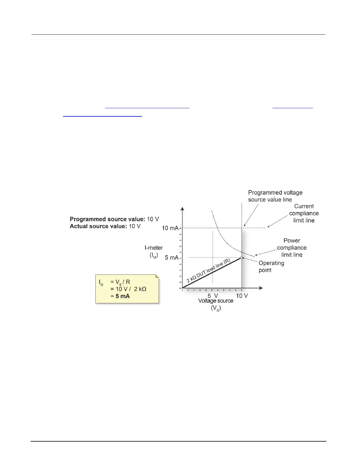
Normal voltage source operation
In the following figure, the 2601B-PULSE is sourcing 10 V to the 2 kΩ load and subsequently
measures 5 mA. The instrument is programmed to limit power (60 mW). As shown, the load line for
2 kΩ intersects the 10 V voltage source line at 5 mA. The current compliance limit and the power
compliance limit are not reached, so the instrument is not limited through its compliance settings.
Figure 104: Normal voltage source operation
Voltage source operation in current compliance
In the following figure, the resistance of the load is decreased to 800 Ω. The DUT load line for 800 Ω
intersects the current compliance limit line, placing the 2601B-PULSE in compliance. When it is in
compliance, the 2601B-PULSE cannot source its programmed voltage (10 V). For the 800 Ω DUT,
the 2601B-PULSE only outputs 8 V (at the 10 mA limit).
Notice that as resistance decreases, the slope of the DUT load line increases. At zero resistance
(shorted output), the 2601B-PULSE sources virtually 0 V at 10 mA. Conversely, as resistance
increases, the slope of the DUT load line decreases. As resistance approaches infinity (open output),
the 2601B-PULSE sources virtually 10 V at 0 mA.

 Loading...


