Section 13: Calibration Model 2601B-PULSE System SourceMeter Instrument Reference Manual
13-34 2601B-PULSE-901-01A April 2020
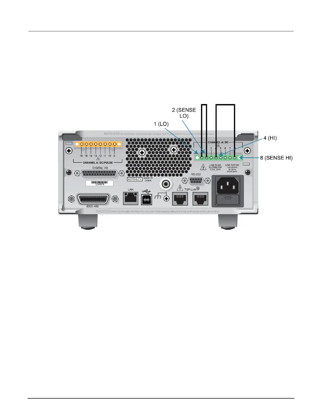
Step 4. Contact check adjustment
A. As illustrated in the following figure:
▪ Short the 2601B-PULSE SENSE LO and LO terminals together.
▪ Short the SENSE HI and HI terminals together.
Figure 161: Connections for contact check 0 Ω calibration
B. Allow the readings to settle, then get the 2601B-PULSE readings:
r0_hi, r0_lo = smua.contact.r()
C. Characterize both 50 Ω resistors using the resistance function of the digital multimeter.
D. As illustrated in the following figure:
▪ Characterize both 50 Ω resistors using the resistance function of the digital multimeter.
▪ Connect a 50 Ω resistor between the SENSE LO and LO terminals.
▪ Connect the second 50 Ω resistor between the SENSE HI and HI terminals.

 Loading...


