Model 2601B-PULSE System SourceMeter Instrument Reference Manual Section 7: Theory of operation
2601B-PULSE-901-01A April 2020 7-7
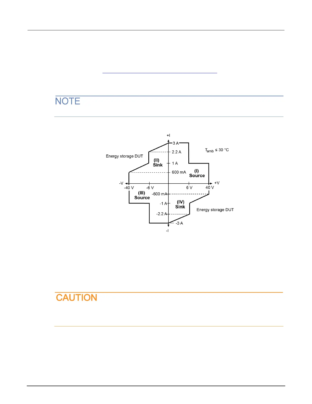
Continuous power operating boundaries
The general operating boundaries for continuous power output are shown in the following figure (for
derating factors, see General power and maximum duty cycle equations (on page 7-2)). In this
drawing, the current (600 mA, 1 A, 2.2 A, and 3 A) and the voltage (6 V and 40 V) magnitudes are
nominal values.
The boundaries are not drawn to scale.
Figure 101: Continuous power operating boundaries when the pulser is disabled
Operation as a sink
When the 2601B-PULSE is operating in the second quadrant or fourth quadrant, the SMU operates
as a load that sinks and dissipates power internally. The ability of the SMU to dissipate power is
defined by the boundaries shown in the previous figure. When the SMU is operating in the second or
fourth quadrant, the DUT is a power source (such as a battery, solar cell, or a power supply).
Use care when connecting a source to the 2601B-PULSE that can exceed the voltage or
current limit. Using the 2601B-PULSE to sink more than 3 A dc can damage the instrument
and invalidate your warranty.

 Loading...


