Model 2601B-PULSE System SourceMeter Instrument Reference Manual Section 13: Calibration
2601B-PULSE-901-01A April 2020 13-3
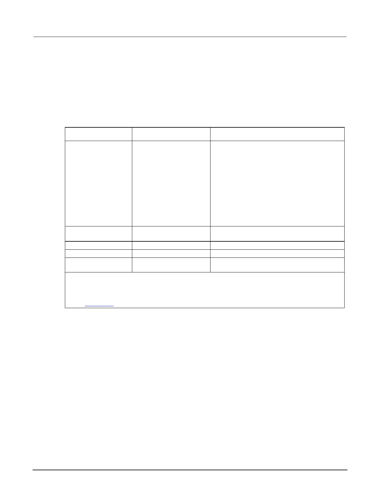
Recommended calibration equipment
The following table summarizes recommended maximum allowable test equipment uncertainty for
calibration points. Total test equipment measurement uncertainty should meet or be less than the
listed values at each test point. Generally, test equipment uncertainty should be at least four times
better than corresponding 2601B-PULSE specifications.
Recommended calibration equipment
Keithley Instruments Model
2002
or
Keysight 3458A
90 mV:
0.9 V:
5.4 V:
36 V:
90 nA:
0.9 mA:
9 µA:
90 µA:
0.9 mA:
9 mA:
90 mA:
0.9 A:
±8 ppm
±5 ppm
±4 ppm
±6 ppm
±430 ppm
±45 ppm
±25 ppm
±23 ppm
±20 ppm
±20 ppm
±35 ppm
±110 ppm
0.5 Ω, 250 W, 0.1%
precision resistor
Isotek
RUG-Z-R500-0.1-TK3
10 Ω, 10 V, 1% pulse
load
1. Ninety-day specifications show full-range accuracy of recommended model used for specified measurement
point.
2. Resistor used to test 3 A range only should be characterized to uncertainty shown using resistance function
of digital multimeter before use.
3. See Pulse loads (on page 13-3) for detail on creating pulse loads.
Pulse loads
You will need pulse loads for the pulse accuracy and bias source accuracy calibrations and
adjustments. The connections are the same for both pulse loads, but the resistor value is different.
For the pulse accuracy procedures, R1 and R2 are 2 ohm resistors. For the bias accuracy procedures,
R1 and R2 are 20 ohm resistors.
The connector to mate with the rear panel CHANNEL A: DC/PULSE connector is Phoenix Contact
connector part number 1825378 (Tek part number 131930700). Recommended wire size is 22 AWG.

 Loading...


