Section 7: Theory of operation Model 2601B-PULSE System SourceMeter Instrument Reference Manual
7-18 2601B-PULSE-901-01A April 2020
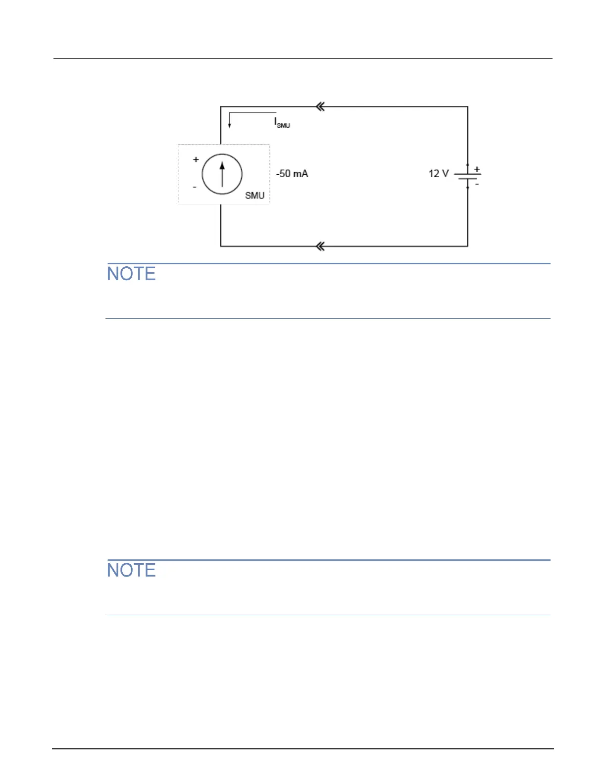
Figure 116: Sourcing current sink operation example
The voltage compliance limit applies both to positive and negative voltages. For example, if you set
the voltage compliance limit to 15 V, the voltage limit applies to ±15 V.
For this example, the 2601B-PULSE is programmed to source −50 mA (the constant current) and to
limit voltage to 15 V. When the SMU turns on, it begins sinking current as determined by the
programmed current source level (−50 mA), causing a decrease in battery voltage. If the battery were
ideal and could be charged negatively, its voltage would continue to decrease until it is negatively
charged at −15 V (shown by the green arrow in the following figure), at which point the SMU would be
in voltage compliance.
Make sure to take into account that reversing the polarity may destroy some power sources. To
prevent a negative charge, monitor the SMU’s measurement of the battery voltage and stop the
discharge before the 2601B-PULSE starts to operate in quadrant III (negative voltage). You can stop
the discharge by changing the programmed current source level or by disconnecting the SMU from
the device.
In the following figure, as the battery drains, the battery voltage is lowered as shown by the green
arrow. Operation will continue in this direction until the user stops operation or the voltage reaches
the voltage compliance limit line.
Since the battery is a power source, operation in this example is limited by the capability of the
battery to deliver 50 mA (see the following figure).

 Loading...


