Phaser 6128MFP Service Manual A-3
Reference
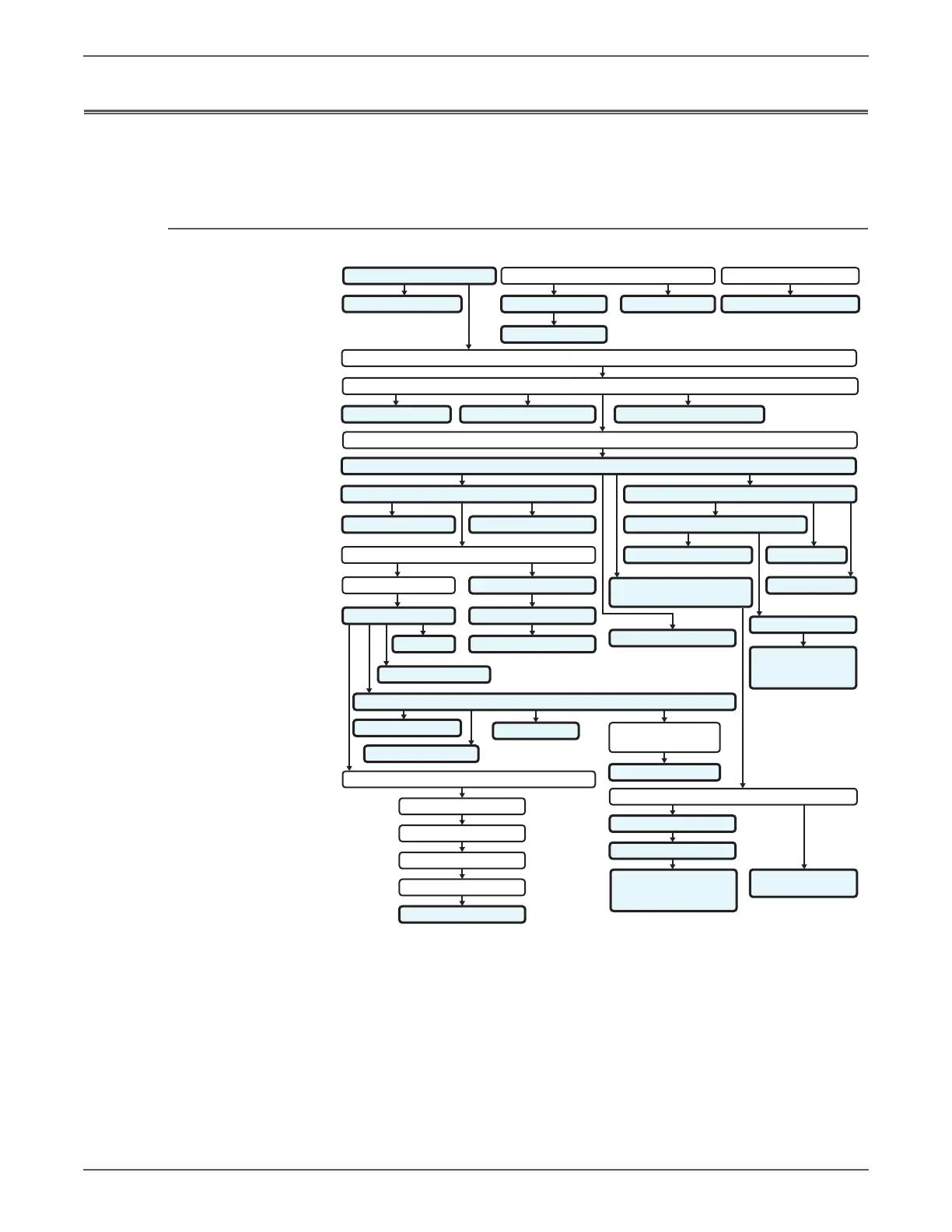
Procedural Flow Diagrams
These diagrams illustrate procedural flow for component removal and
replacement. Components not connected with arrows can be removed or installed
independently.
Removal Flow Diagrams
Separator Roller
250-Sheet Tray
Rear Cover
ESS Shield
Fax Board
Imaging Processor Board
Outer Pole Cover
Feed Roller Manual Feed No Paper Sensor Manual Feed Sensor Actuator
ESS Cover
Feed Drive Assembly
Gear P2
Main Drive
Interlock Harness
Sub Drive
Right Side Cover
Right Side Door
Right Side Cover
Rear Cover
Top Cover
Imaging Unit
Fuser
Left Side Cover
Front Cover
Toner Cartridge (K),(C),(M),(Y)Imaging Unit
Front Cover
Control Panel
Right Side Door
Fuser
Erase LED Assembly
Imaging Unit
Springs, Levers,
Restraint Blocks
LVPS
Fan
Drive Clutch,
Registration Bearing
Drive Clutch,
Registration Bearing
Humidity Sensor
Lower Scanner Cover
Switch
Interlock Harness
Gear P2
Tray 1 (MPT)
Feed Solenoid
Main Drive
Feed Drive Assembly
Drive Clutch, Registration Bearing
Power Switch Harness
GFI Breaker
MCU Board
Feed Drive Assembly
LVPS Card Cage
s6128mfp-304
Imaging Unit
Springs, Levers,
Restraint Blocks
 Loading...