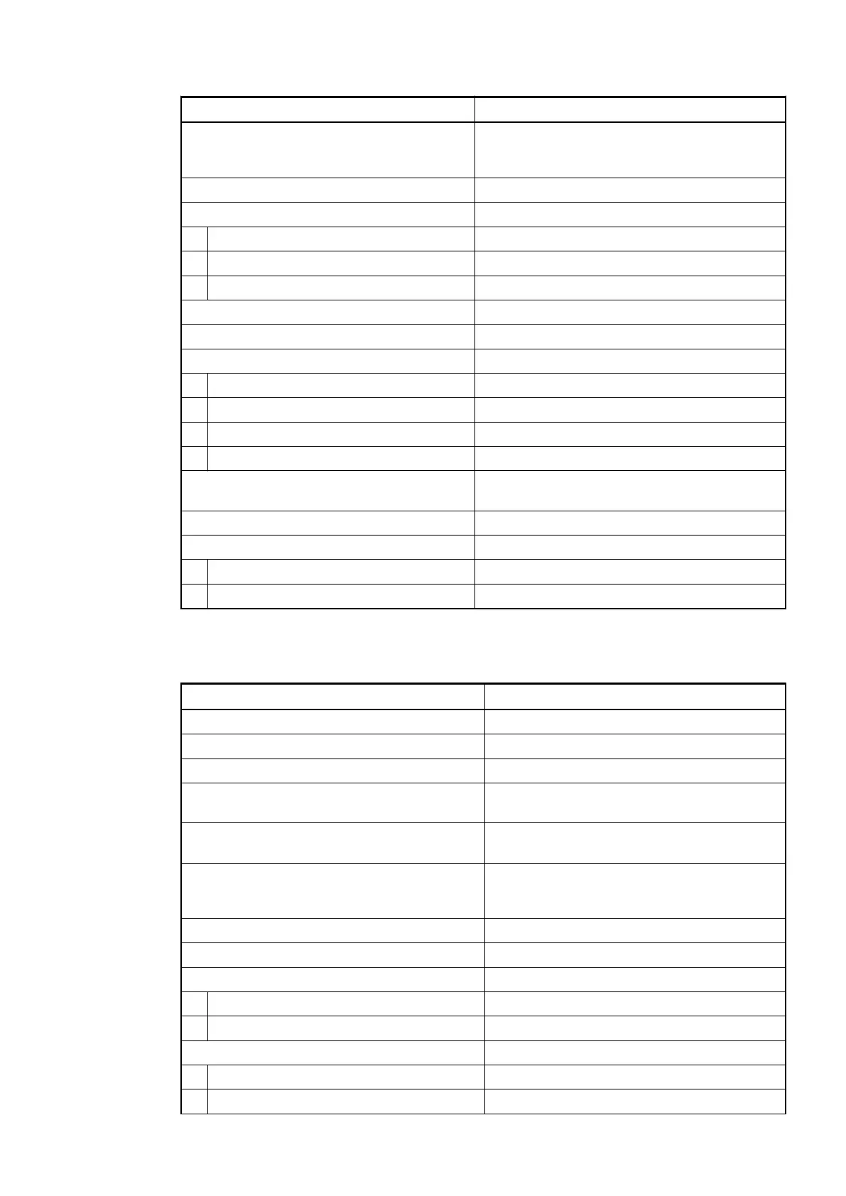
Parameter Value
Indication of the input signals 1 yellow LED per channel; the LED is ON when
the input signal is high (signal 1). The module is
powered via the I/O bus.
Input type according to EN 61131-2 Type 1 sink
Input signal range +24 V DC
Signal 0 -3 V...+5 V
Undefined signal +5 V...+15 V
Signal 1 +15 V...+30 V
Ripple with signal 0 -3 V...+5 V
Ripple with signal 1 +15 V...+30 V
Input current per channel
Input voltage +24 V Typ. 5 mA
Input voltage +5 V Typ. 1 mA
Input voltage +15 V > 2.5 mA
Input voltage +30 V < 8 mA
Max. permissible leakage current (at 2-wire
proximity switches)
1 mA
Input delay (0->1 or 1->0) Typ. 8 ms
Max. cable length
Shielded 500 m
Unshielded 300 m
Technical data of the digital inputs/outputs if used as outputs
Parameter Value
Number of channels per module 16 configurable transistor outputs
Distribution of the channels into groups 1 (16 channels per group)
Connections of the channels C0 to C15 Terminals 1 to 16
Reference potential for the channels C0 to
C15
Terminals 18 and 20 (negative pole of the
process voltage, signal name ZP)
Common power supply voltage Terminals 17 and 19 (positive pole of the
process voltage, signal name UP)
Indication of the input signals 1 yellow LED per channel; the LED is ON
when the input signal is high (signal 1). The
module is powered via the I/O bus.
Way of operation Non-latching type
Output voltage at signal 1 UP -0.3 V at max. current
Output delay (max. at rated load)
0 to 1 50 µs
1 to 0 200 µs
Output current
Rated current per channel (max.) 0.1 A at UP 24 V DC
Rated current per group (max.) 1.6 A
I/O modules > Digital I/O modules
2022/01/31 3ADR010278, 3, en_US 149