GSD file:
Ext_User_Prm_Data_Len =
Ext_User_Prm_Data_Const
(0) =
7
0x04, 0xbb, 0x04, \
0x01, 0x02, 0x00, 0x00;
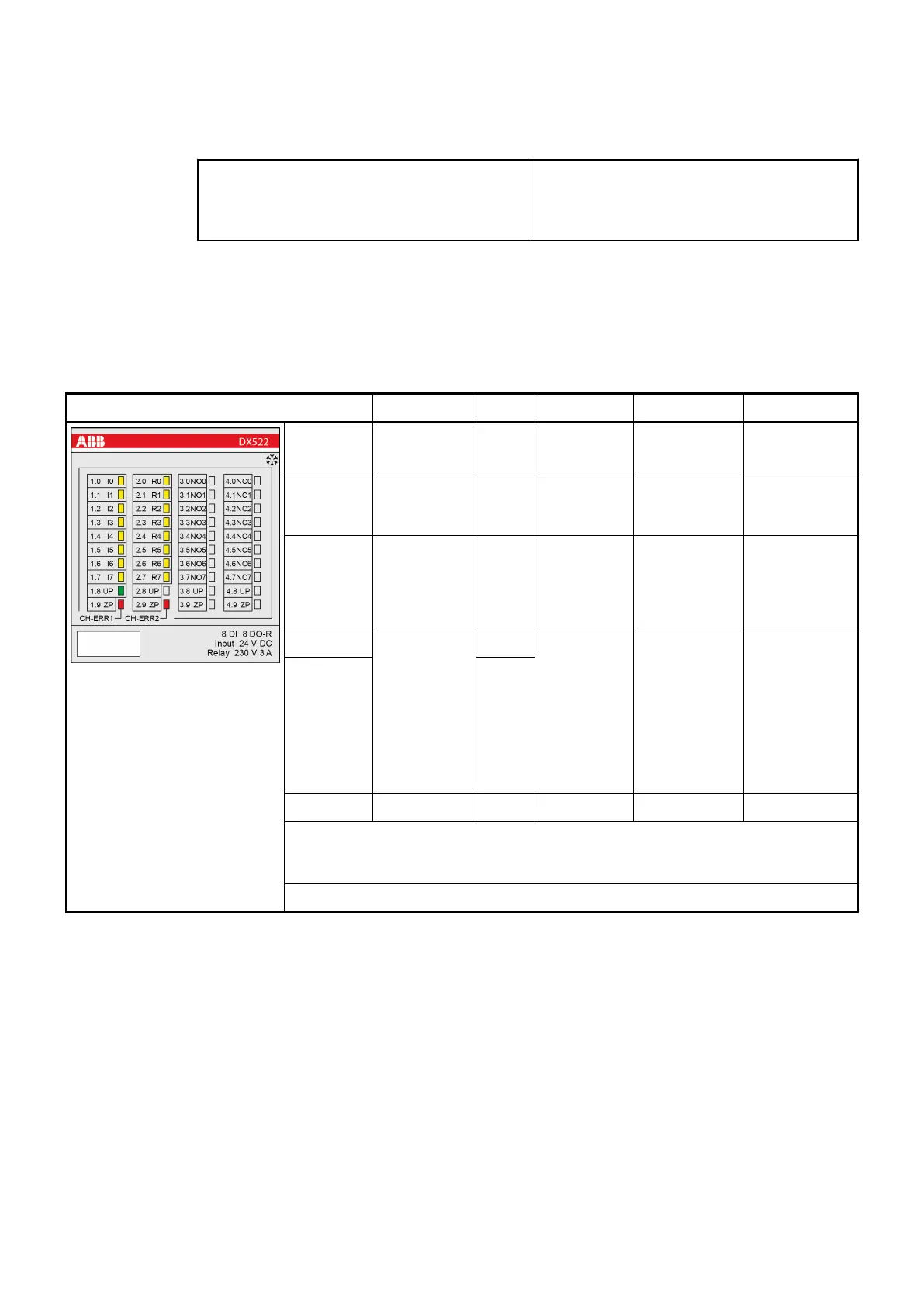
State LEDs
During the power ON procedure, the module initializes automatically. All LEDs (except the
channel LEDs) are ON during this time.
LED State Color LED = OFF LED = ON LED flashes
Inputs
I0...I7
Digital input Yellow Input = OFF
Input = ON
1
)
--
Outputs
R0...R7
(relays)
Digital output Yellow Relay output
= OFF
Relay output =
ON
--
UP Process
supply
voltage
24 V DC via
terminal
Green Process
supply
voltage is
missing
Process
supply voltage
OK
--
CH-ERR1 Channel
Error, error
messages in
groups (dig-
ital inputs/
outputs com-
bined into the
groups 1 and
2)
Red No error or
process
supply
voltage is
missing
Severe error
within the cor-
responding
group
Error on one
channel of the
corresponding
group
CH-ERR2 Red
CH-ERR
2
)
Module Error Red -- Internal error --
1
) Indication LED is ON even if an input signal is applied to the channel and
the supply voltage is off. In this case the module is not operating and does not
generate an input signal.
2
) All of the LEDs CH-ERR1 to CH-ERR2 light up together
Technical data
The system data of AC500 and S500
Ä
Chapter 2.6.1 “System data AC500” on page 971 are
applicable to the standard version.
The system data of AC500-XC
Ä
Chapter 2.7.1 “System data AC500-XC” on page 1023 are
applicable to the XC version.
Only additional details are therefore documented below.
The technical data are also applicable to the XC version.
I/O modules > Digital I/O modules
2022/01/31 3ADR010278, 3, en_US 335