Connection of active-type analog sensors (Voltage) with galvanically isolated power supply to the analog
inputs
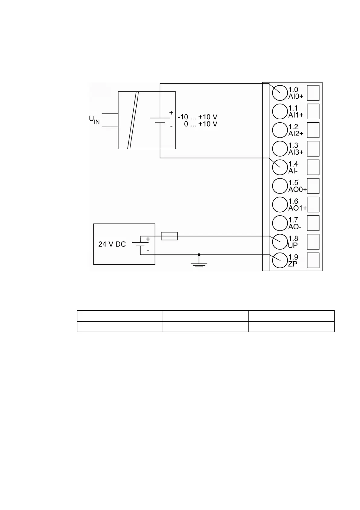
The following figure shows the connection of active-type analog sensors (voltage) with galvani-
cally isolated power supply to the analog input AI0. Proceed with the analog inputs AI1 to AI3 in
the same way.
The following measuring ranges can be configured
Ä
Chapter 1.7.5.2.7 “Parameterization”
on page 815
Ä
Chapter 1.7.5.2.9.1 “Input ranges voltage, current and digital input”
on page 828:
Voltage 0 V...10 V 1 channel used
Voltage -10 V...+10 V 1 channel used
The function of the LEDs is described under Diagnosis and displays / Displays
Ä
Chapter
1.7.5.2.8 “Diagnosis and state LEDs” on page 821.
To avoid error messages from unused analog input channels, configure them as "unused".
Connection of active-type analog sensors (Current) with galvanically isolated power supply to the analog
inputs
The following figure shows the connection of active-type analog sensors (current) with galvani-
cally isolated power supply to the analog input AI0. Proceed with the analog inputs AI1 to AI3 in
the same way.
Communication interface modules (S500) > PROFINET
2022/01/313ADR010278, 3, en_US806