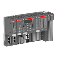
1.7.4.2.1 Intended purpose
Modbus TCP communication interface module CI522-MODTCP is used as decentralized I/O
module in Modbus TCP networks. The network connection is performed via 2 RJ45 connectors
which are integrated in the terminal unit. The communication interface module contains 24 I/O
channels with the following properties:
● 8 digital configurable inputs/outputs in 1 group (1.0...1.7)
● 8 digital inputs 24 V DC in 1 group (2.0...2.7)
● 8 digital outputs 24 V DC in 1 group (3.0...3.7)
The inputs/outputs are galvanically isolated from the Ethernet network. There is no potential
separation between the channels. The configuration of the configurable digital inputs/outputs is
performed by software.
For usage in extreme ambient conditions (e.g. wider temperature and humidity range), a special
XC version of the device is available.
1.7.4.2.2 Functionality
Interface Ethernet
Protocol Modbus TCP
Power supply From the process supply voltage UP
Supply of the electronic circuitry of the I/O
expansion modules attached
Through the I/O bus interface (I/O bus)
Rotary switches for setting the last BYTE of the IP ADDRESS
(00h to FFh)
Configurable digital inputs/outputs 8 (configurable via software)
Digital inputs 8 (24 V DC; delay time configurable via soft-
ware)
Digital outputs 8 (24 V DC, 0.5 A max.)
LED displays For system displays, signal states, errors and
power supply
External supply voltage Via terminals ZP, UP and UP3 (process supply
voltage 24 V DC)
Required terminal unit
TU507 or TU508
Ä
Chapter 1.5.1 “TU507-
ETH and TU508-ETH for Ethernet communi-
cation interface modules” on page 122
1.7.4.2.3 Connections
The Ethernet bus module CI522-MODTCP is plugged on the I/O terminal unit TU507-ETH
Ä
Chapter 1.5.1 “TU507-ETH and TU508-ETH for Ethernet communication interface modules”
on page 122 or TU508-ETH
Ä
Chapter 1.5.1 “TU507-ETH and TU508-ETH for Ethernet com-
munication interface modules” on page 122. Properly seat the module and press until it locks in
place. The terminal unit is mounted on a DIN rail or with 2 screws plus the additional accessory
for wall mounting (TA526
Ä
Chapter 1.8.2.6 “TA526 - Wall mounting accessory” on page 902).
The connection of the I/O channels is carried out using the 30 terminals of the I/O terminal unit.
I/O modules can be replaced without re-wiring the terminal units.
For a detailed description of the mounting, disassembly and connection of the
module, please refer to the System Assembly, Construction and Connection
chapter
Ä
Chapter 2.6 “AC500 (Standard)” on page 971.
Communication interface modules (S500) > Modbus
2022/01/31 3ADR010278, 3, en_US 771

 Loading...