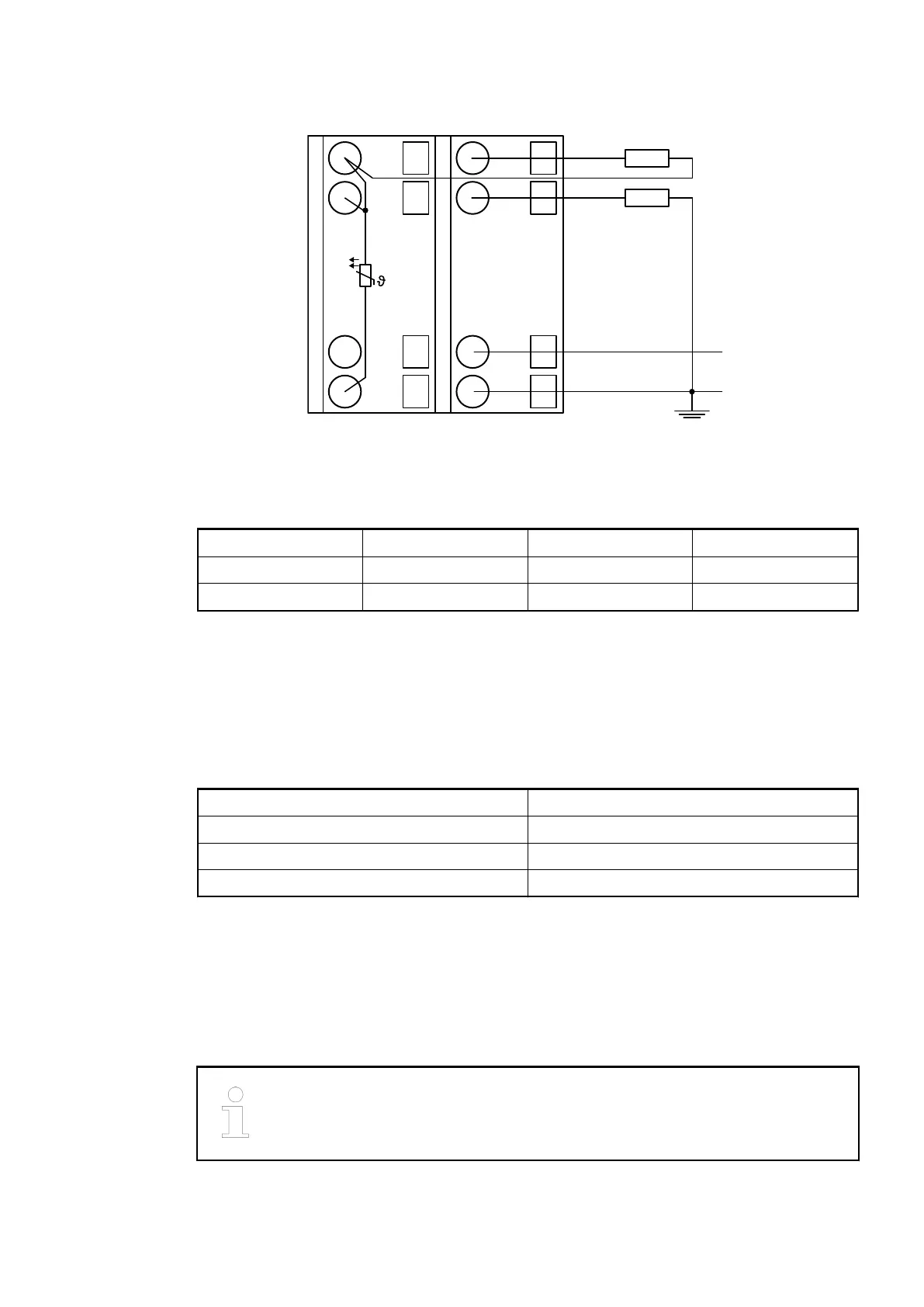
Connection of analog output loads (Voltage, current)
UP
ZP
1.0
O0-
1.1
O1-
1.8
UP
1.9
ZP
PTC
2.0
O0+
2.1
O1+
2.8
UP
2.9
ZP
-10 ... +10 V
0 ... 20 mA
4 ... 20 mA
Fig. 51: Connection example
The following measuring ranges can be configured
Ä
Chapter 1.6.2.2.4.6 “Parameterization”
on page 491:
Voltage -10 V...+10 V Load max. ±10 mA 1 channel used
Current 0 mA...20 mA Load 0 W...500 W 1 channel used
Current 4...20 mA Load 0 W...500 W 1 channel used
Only the channels 0...3 and 8...11 can be configured as current output (0 mA...20 mA or 4
mA...20 mA).
The function of the LEDs is described under Displays.
Unused analog outputs can be left open-circuited.
Internal data exchange
Digital inputs (bytes) 0
Digital outputs (bytes) 0
Counter input data (words) 0
Counter output data (words) 16
I/O configuration
The module does not store configuration data itself. It gets its parameterization data from the
master device of the I/O bus (CPU or communication interface module) during power-up of the
system.
That means replacing I/O modules is possible without any re-parameterization via software.
If the external power supply voltage via UP/ZP terminals fails, the I/O module
loses its configuration data. The whole station has to be switched off and on
again to re-configure the module.
I/O modules > Analog I/O modules
2022/01/313ADR010278, 3, en_US490

 Loading...