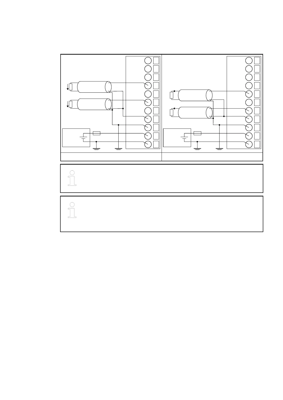
The following figures are an example of the connection of analog actuators to the analog input/
output module AX561.
24 V DC
-
+
10
11
R3
I3+
13
O0U+
12
I3-
14
O0I+
15
O1U+
16
O1I+
17
O01-
18
SG
19
L+
20
M
U
U
24 V DC
-
+
10
11
R3
I3+
13
O0U+
12
I3-
14
O0I+
15
O1U+
16
O1I+
17
O01-
18
SG
19
L+
20
M
I
I
Connection of analog voltage actuators Connection of analog current actuators
The output signal is undefined if the supply voltage at the L+ terminal is below
10 V. This can, for example, occur if the supply voltage has a slow ramp-up /
ramp-down behavior and must be foreseen when planning the installation.
If the output is configured in current mode, the voltage output signal is unde-
fined and must not be connected.
If the output is configured in voltage mode, the current output signal is unde-
fined and must not be connected.
The meaning of the LEDs is described in the displays chapter
Ä
Chapter 1.6.2.1.5.7 “State
LEDs” on page 401.
I/O configuration
The I/O module does not store configuration data itself.
Parameterization
The arrangement of the parameter data is performed with Automation Builder software.
The parameter data directly influences the functionality of modules.
For non-standard applications, it is necessary to adapt the parameters to your system configura-
tion.
I/O modules > Analog I/O modules
2022/01/313ADR010278, 3, en_US398