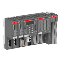
Table 154: States of the 29 process LEDs
LED Color OFF ON Flashing
DC0 to DC7 Yellow Input/Output is
OFF
Input/Output is
ON
--
DI8 to DI15 Yellow Input is OFF Input is ON (the
input voltage is
even displayed if
the supply
voltage is OFF)
--
DO8 to DO15 Yellow Output is OFF Output is ON --
UP Green Process supply
voltage missing
Process supply
voltage OK and
initialization fin-
ished
--
UP3 Green Process supply
voltage missing
Process supply
voltage OK
--
CH-ERR1 to CH-
ERR3
Red No error or
process supply
voltage missing
Internal error Error on one
channel of the
corresponding
group
1.7.3.2.11 Technical data
The system data of AC500 and S500
Ä
Chapter 2.6.1 “System data AC500” on page 971 are
applicable to the standard version.
The system data of AC500-XC
Ä
Chapter 2.7.1 “System data AC500-XC” on page 1023 are
applicable to the XC version.
Only additional details are therefore documented below.
The technical data are also applicable to the XC version.
Parameter Value
Bus connection 2 x RJ45
Technology Hilscher NETX 100
Transfer rate 10/100 Mbit/s (full-duplex)
Transfer method According to Ethernet II, IEEE 802.3
Ethernet 100 base-TX, internal switch, 2x RJ45 socket
Expandability (S500 I/O modules) Up to 10 S500 I/O modules (Index C0 and
above), not available (Index below C0)
Indicators 5 LEDs for state indication
Adjusting elements 2 rotary switches (used for future topology
extensions)
Quantity of input/output data CI512-ETHCAT: 10 bytes input and 14 bytes
output
CI511-ETHCAT: 18 bytes input and 18 bytes
output
Limit of data for input and output 144 byte
Communication interface modules (S500) > EtherCAT
2022/01/31 3ADR010278, 3, en_US 723

 Loading...