10-13
DS35-W00 May. 2007
CLUTCHCLUTCH
CLUTCHCLUTCH
CLUTCH
TRANSMISSIONTRANSMISSION
TRANSMISSIONTRANSMISSION
TRANSMISSION
ENGINEENGINE
ENGINEENGINE
ENGINE
HSTHST
HSTHST
HST
FRONT AXLEFRONT AXLE
FRONT AXLEFRONT AXLE
FRONT AXLE
STEERINGSTEERING
STEERINGSTEERING
STEERING
BARKEBARKE
BARKEBARKE
BARKE
ELECTRICELECTRIC
ELECTRICELECTRIC
ELECTRIC
INDEXINDEX
INDEXINDEX
INDEX
HYDRAULICHYDRAULIC
HYDRAULICHYDRAULIC
HYDRAULIC
GENERALGENERAL
GENERALGENERAL
GENERAL
REAR AXLEREAR AXLE
REAR AXLEREAR AXLE
REAR AXLE
CK22/CK22H
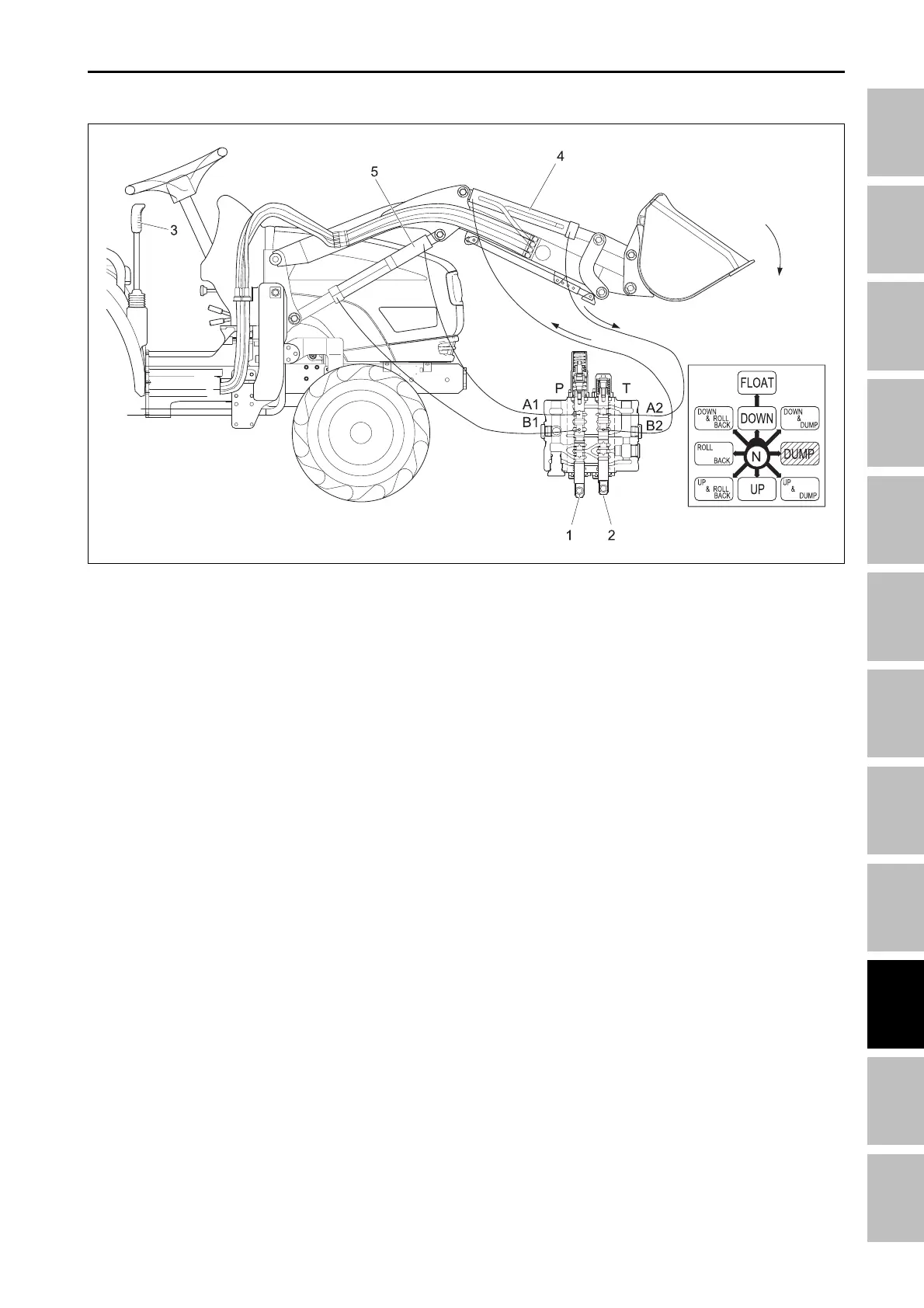
A. DUMP POSITION
(1) Lift control valve spool
(2) Bucket control spool
(3) Control lever
(4) Bucket cylinder
(5) Lift cylinder
When the control lever (3) is moved to the dumping
position, the bucket control spool (2) is moved inward.
Fluid flow from the hydraulic pump is directed to the
piston side of the bucket cylinder (4).
The fluid contained in the rod side of the bucket cylin-
der flows out of the cylinder through passage “A2” exit-
ing the valve at port “T” and flows to the transmission
case.
196W919A
HYDRAULIC SYSTME - OPERATING PRINCIPLE