OPERATION
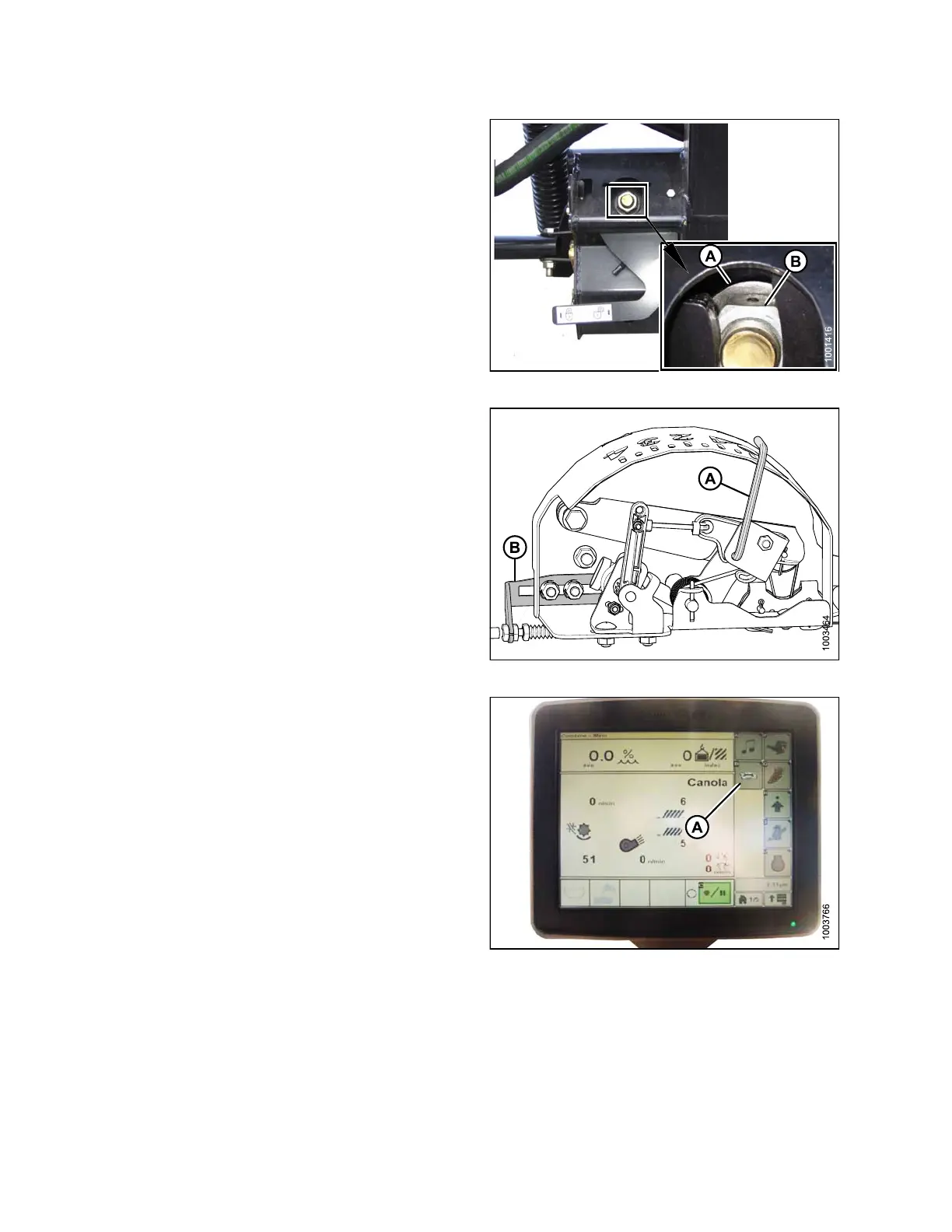
2. Check that float lock linkage is on down stops
(washer [A] and nut [B] cannot be moved) at both
locations.
NOTE:
If the header is not on down stops during the next
two steps, the voltage may go out of range during
operation causing a malfunction of the AHHC system.
Figure 3.198: Float Lock
3. Adjust the cable take-up bracket (B) (if necessary) until
the pointer (A) on the float indicator is on ‘0’.
Figure 3.199: Float Indicator Box
4. Press the CALIBRATION icon (A) on the main page of
the monitor. The CALIBRATION page appears.
Figure 3.200: Combine Display
147695
1
44
Revision A