HEADER ATTAC HMENT/D ETACH ME NT
2. Engage both float locks by moving lever (A) upwards
at each lock until it latches in to lock pos ition.
Figure 4.
13: Float Locked
IMPORTANT:
If slow speed transport wheels are installed, header
may be detached in either Transport or Field mode.
If detaching with wheel in Field mode, set wheels to
storage or uppermost working position; otherwise,
header may tilt forward so that reattachment will be
difficult. Refer to 3.7.1 Cutting Height, page 52.
IMPORT
ANT:
If stab
ilizer whee ls are installe d, set wh eels to storage
or uppe
rmost working position. Otherwise header
may ti
lt forward so that reattachment will be difficult.
Refer
to 3.7.1 Cutting Height, page 52.
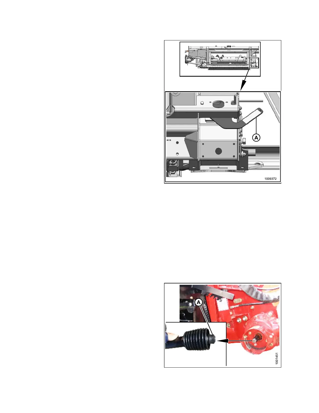
3. Disconn ect d
riveline (A) from combine.
Figure 4.14: Driveline
147695 204 Revision A