HEADER ATTA CHMEN T/DETACHMENT
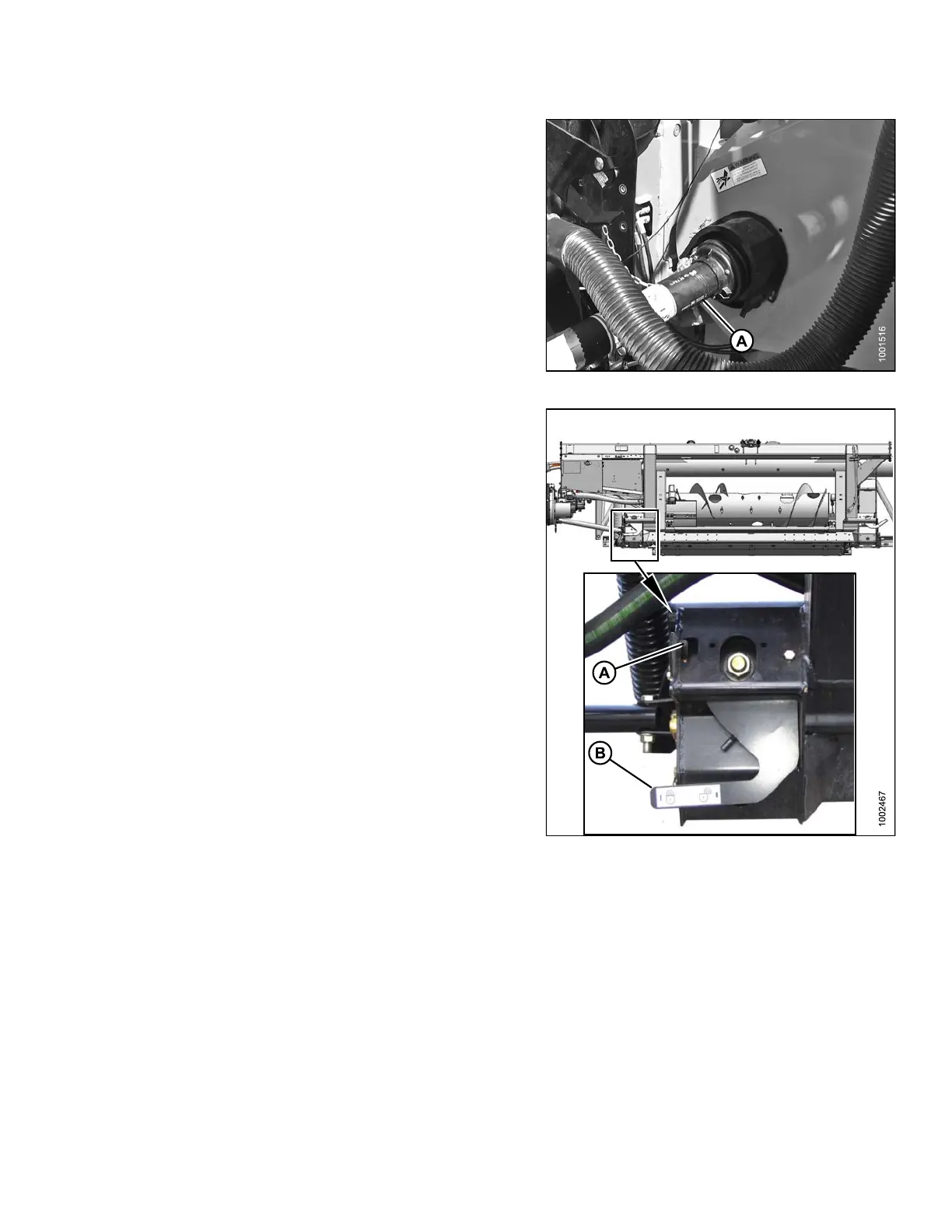
15. Attach driveline (A) to combine output shaft.
Figure 4.44: Driveline and Output Shaft
16. Disengage both adapter float locks by moving latch (A)
away from adapter and moving both header floa t lock
levers (B) down (UNLOCK).
Figur
e 4.45: Float Lock in UNLOCK Position
147695
2
17
Revision A