HEADER ATTA CHMEN T/DETACHMENT
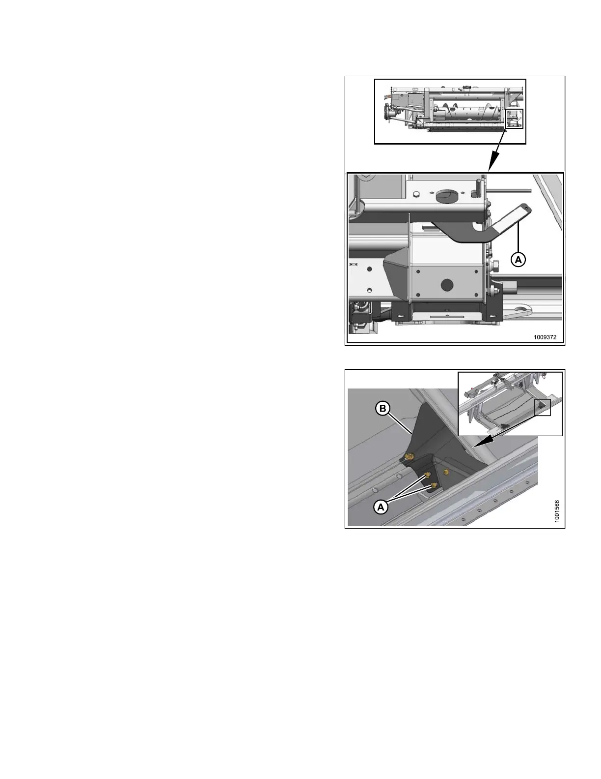
5. Engage the float locks by lifting lever (A) until it latches
into the lock position.
NOTE:
Stabilizer/Slow Speed Transport wheels can be
used to support header.
Figure 4.
100: Float Locked
6. Remove two hex head bolts (A) attaching filler (B) to
transition pan at front co rners, fold back filler (B) for
access to latch, shown in next image.
Figur
e 4.101: Fillers
147695
2
41
Revision A