OPERATION
Adjusting Stabilizer/Slow Speed Transport Wheels
The proper setting requires balancing the amount of header weight carried by the float and th e s tabilizer/slow
speed transport wheels.
Refer to 3.6.2 Header Settings, page 44 for recommended use in specific crops and crop conditions.
DANGER
To avoid bodily injury or death from unexpected start-up of m achine, always stop engine and remove key
from ignition before leaving operator’s seat for any reason.
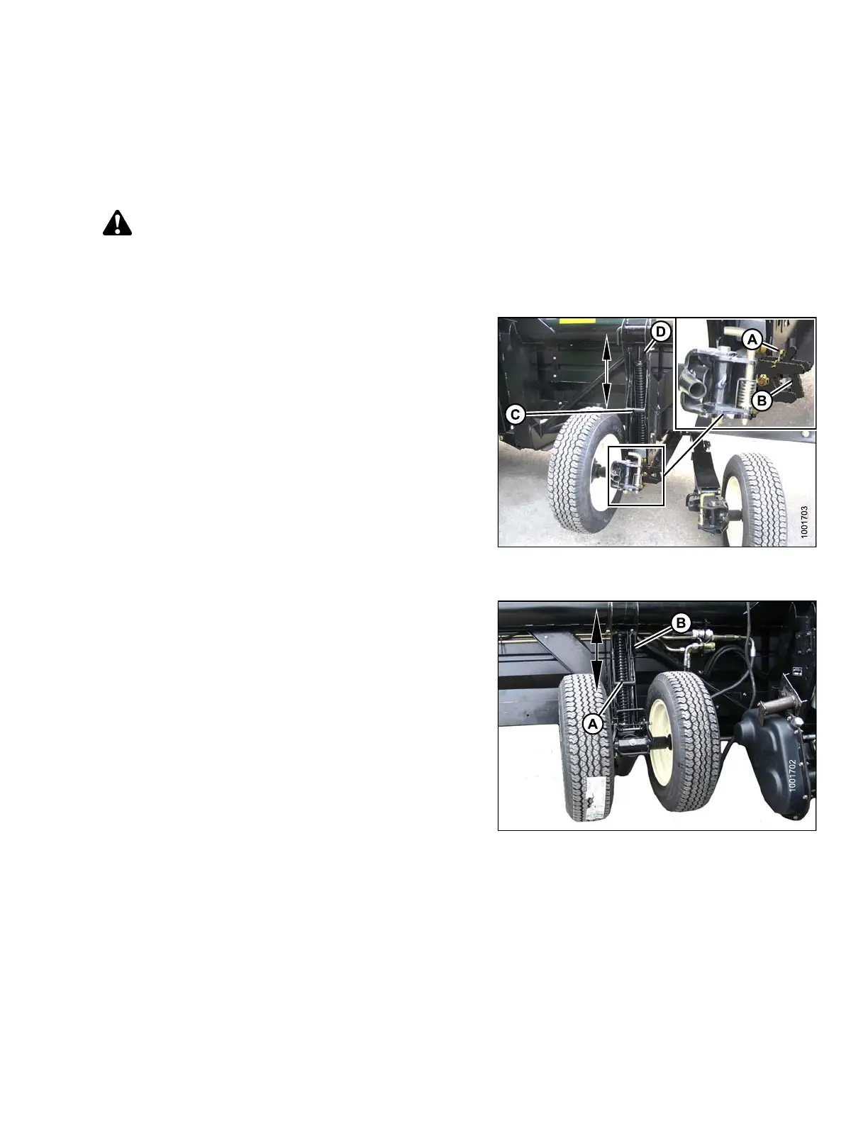
1. Raise the header so that the stabilizer wheels are off the g rou nd. S h u t down engine an d remove the key.
2. On the right wheel assembly, remove hairpin (A)
from latch.
3. Disengage latch (B) and lift right wheel out of hook and
place on ground as shown. This reduces w eight of
assembly and makes adjusting wheel position easier.
4. Support left wheel weight by lifting slightly with one
hand. Pull up on handle (C) to release lock.
5. Lift left wheel to desired height and engage support
channel into slot (D) in upper support.
6. Push down on handle (C) to lock.
7. Lift right wheel back into field position and ensure
latch (B) is engaged.
8. Secure latch with hairpin (A).
Figure 3.24: Right Wheel
9. Support the left wheel assembly’s wheel weight by
lifting slightly with one hand. Pull up on handle (A) to
release l ock.
10. Lift wheels to desired height and engage support
channel into slot (B) in upper support.
11. Push down on handle (A) to lock.
Figure 3.25: Left Wheel
147695 53 Revision A