OPERATION
2. Support wheel weight by lifting slightly with one hand
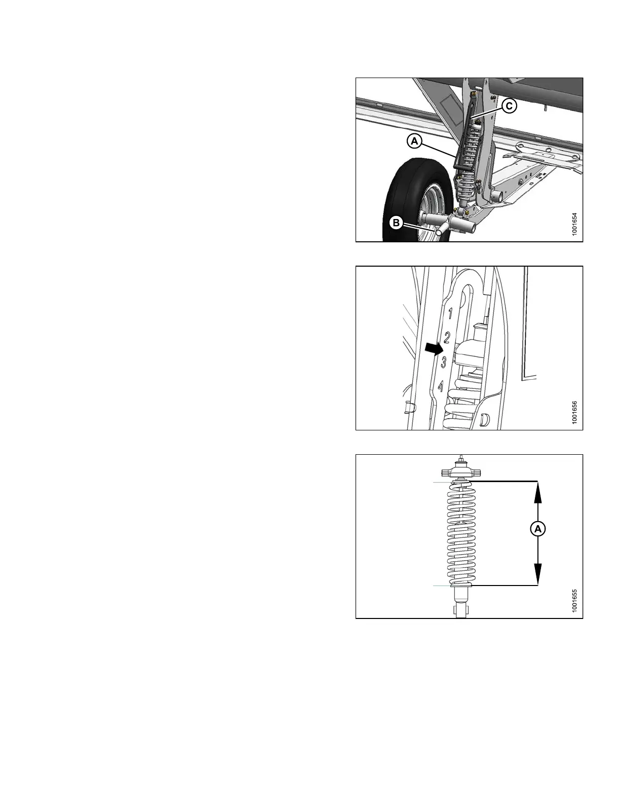
on handle (B). Pull up on handle (A) to release lock.
3. Lift wheel with handle (B) and engage support channel
into center slot (C) in upper support.
4. Push down on handle (A) to lock.
Figure 3.28: Stabilizer Wheel
5. Lower header to desired cutting height using
combinecontrols and check load indicator. As an
example the image shows that the wheels are set to a
range between ‘2’and‘3’ on load indicator.
Figure 3.29: Load Indicator
IMPORT
ANT:
Contin
uous operation with excessive spring
compre
ssion (i.e., load indicator reading greater
than ‘4
’ or a compressed length less than
11-5/8
in. [295 mm]) (A) can result in d amage to
suspe
nsion system .
6. Adjust header angle to desired working angle with the
machine’s header angle controls. If angle is not critical,
set it to mid-pos itio n.
7. Use the combine’s Auto Header Height Control
(AHHC) to automatically maintain c uttin g height. Refer
to 3.8 Auto Header Height Control (AHHC), page 89
and your combine operator’s manual for details.
NOTE:
The height sensor on the CA25 adapter must be
connected to the combine height control system in
the cab.
Figure 3.30: Spring Compression
147695 55 Revision A