4. STARTUP
4 - 11
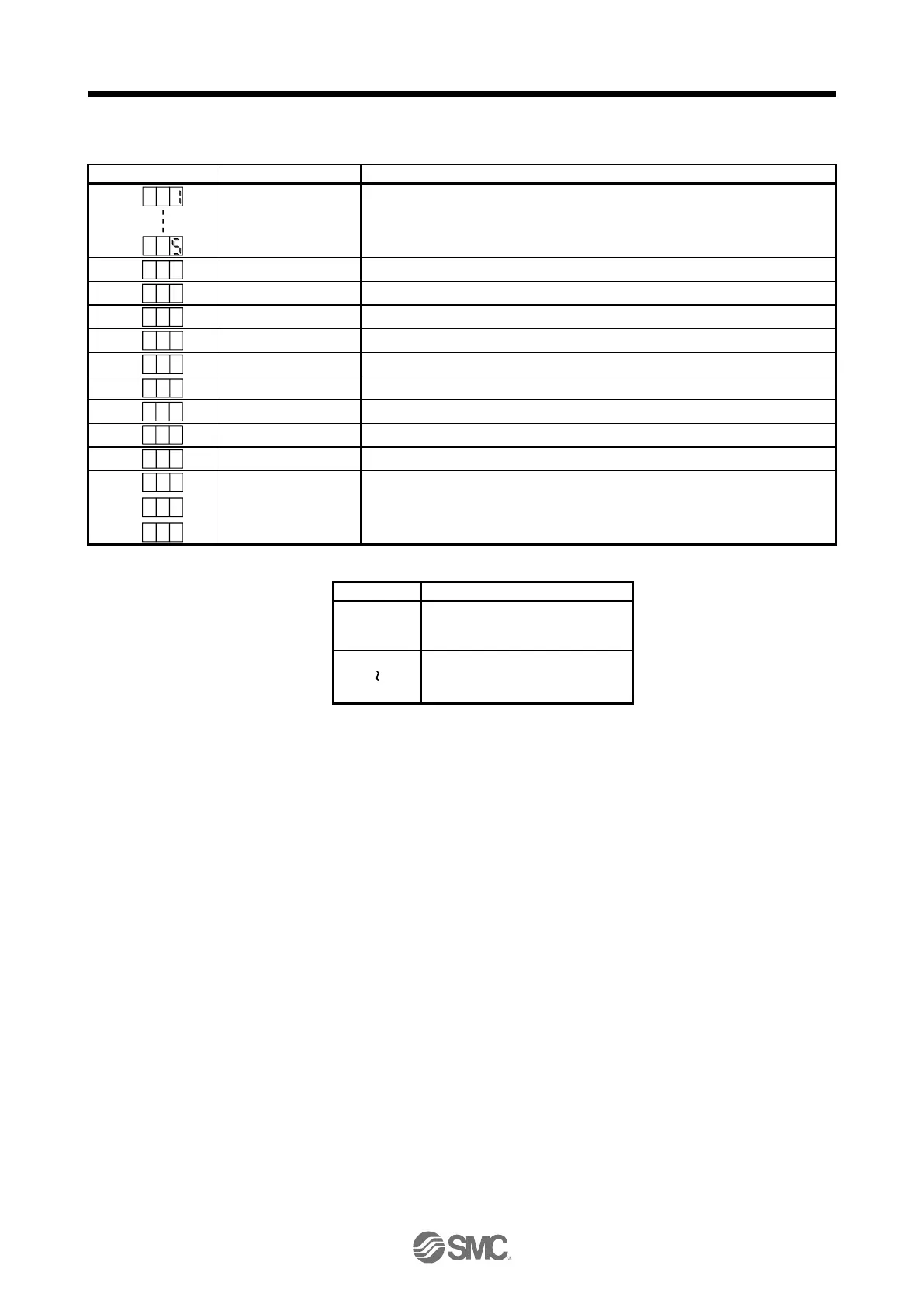
(2) Indication list
No connection with the upper side
During initial communication with the upper side
Communication disconnection with the upper side
The ready-off signal from the upper side was received.
The ready-off signal from the upper side was received.
The ready-off signal from the upper side was received.
An alarm or warning occurred on the driver.
The alarm No. and the warning No. that occurred is displayed. (Refer to chapter 8.)
CPU watchdog error has occurred.
(Note 3)
Test operation mode
During test operation
JOG operation, positioning operation, program operation, output signal (DO) forced
output, motor-less operation, or single-step feed was set.
## is displayed in hexadecimal. The following table shows the description.
For the last 2 digits of axis No. or
automatic setting with the upper
side.
Last 2 digits of axis No.
** indicates the alarm No. and the warning No.
Requires the Setup software (MR Configurator2
TM
)

 Loading...


