3. SIGNALS AND WIRING
3 - 12
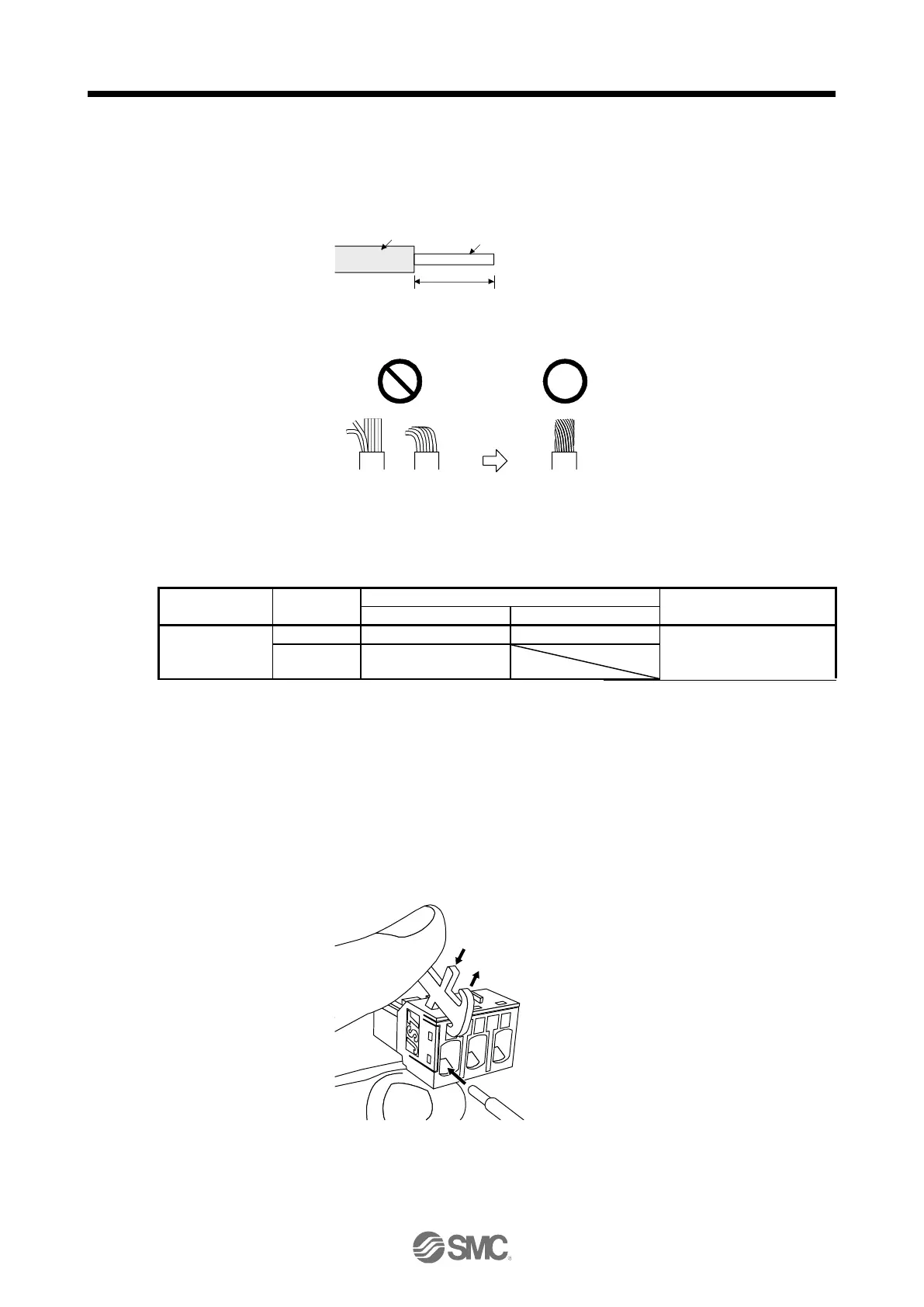
(2) Cable connection procedure
(a) Fabrication on cable insulator
Refer to table 3.1 to 3.4 for stripped length of cable insulator. The appropriate stripped length of
cables depends on their type, etc. Set the length considering their status.
Insulator
Core
Stripped length
Twist strands lightly and straighten them as follows.
Loose and bent strands Twist and straighten
the strands.
You can also use a ferrule to connect with the connectors. The following shows references to
select ferrules according to wire sizes.
Ferrule model (Phoenix Contact)
Crimping tool
(Phoenix Contact)
LECSN
□
-T5
~
LECSN
□
-T8,
LECSN
2
-T9
(b) Inserting wire
Insert only one wire or ferrule to each wire insertion hole.
Insert the open tool as follows and push it down to open the spring. While the open tool is pushed
down, insert the stripped wire into the wire insertion hole. Check the wire insertion depth, and make
sure that the cable insulator will not be caught by the spring and that the conductive part of the
stripped wire will not be exposed.
Release the open tool to fix the wire. Pull the wire lightly to confirm that the wire is surely connected.
In addition, make sure that no conductor wire sticks out of the connector.
The following shows a connection example of the CNP3 connector.
1) Push down the open tool.
3) Release the open tool to fix the w ire.
2) Insert the wire.

 Loading...


