3. SIGNALS AND WIRING
3 - 36
(2) When you do not use the forced stop deceleration function
To disable the function, set "0 _ _ _" in [Pr. PA04].
(a) Servo-on command (from upper side) on/off
It is the same as (1) (a) in this section.
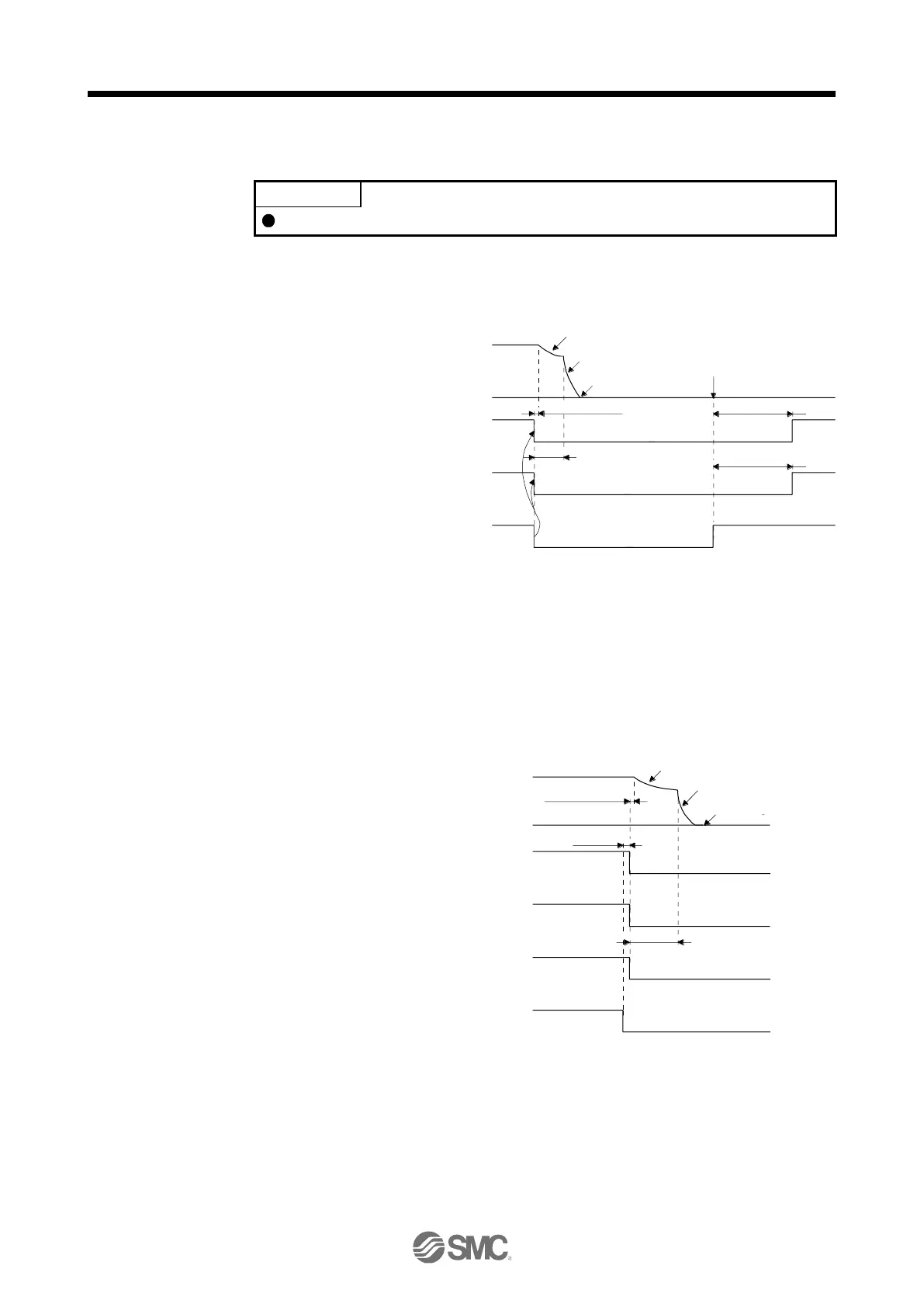
(b) Off/on of the quick stop command (from upper side) or EM1 (Forced stop 1)
Dynamic brake
Dynamic brake
+ Electromagnetic brake
Electromagnetic brake
MBR
(Electromagnetic
brake interlock)
Operation delay time
of the electromagnetic
brake
Approx. 210 ms
Approx. 210 ms
Electromagnetic brake
has released.
(Note)
ON
OFF
Base circuit
ON
OFF
Servo motor speed
Quick stop command
(from controller) or EM2
(Forced stop 1)
ON (Disabled)
OFF (Enabled)
0 r/min
Approx. 10 ms
ON: Lock is not activated.
OFF: Lock is activated.
(c) Alarm occurrence
The operation status during an alarm is the same as section 3.7.2.
(d) Both main and control circuit power supplies off
It is the same as (1) (d) in this section.
(e) Main circuit power supply off during control circuit power supply on
Dynamic brake
Dynamic brake
+ Electromagnetic brake
Electromagnetic brake
Operation delay time of
the electromagnetic brake
MBR
(Electromagnetic
brake interlock)
(Note 2)
Base circuit
Alarm
[AL. 10 Undervoltage]
No alarm
Alarm
Servo motor speed
Approx. 10 ms
(Note 1)
ON
OFF
ON
OFF
Main circuit
pow er supply
ON
OFF
0 r/min
Variable according to the operation status.
ON: Lock is not activated.
OFF: Lock is activated.
(f) Ready-off command from upper side
It is the same as (1) (f) in this section.

 Loading...


