Phaser 4500/4510 Service Manual 8-9
FRU Disassembly
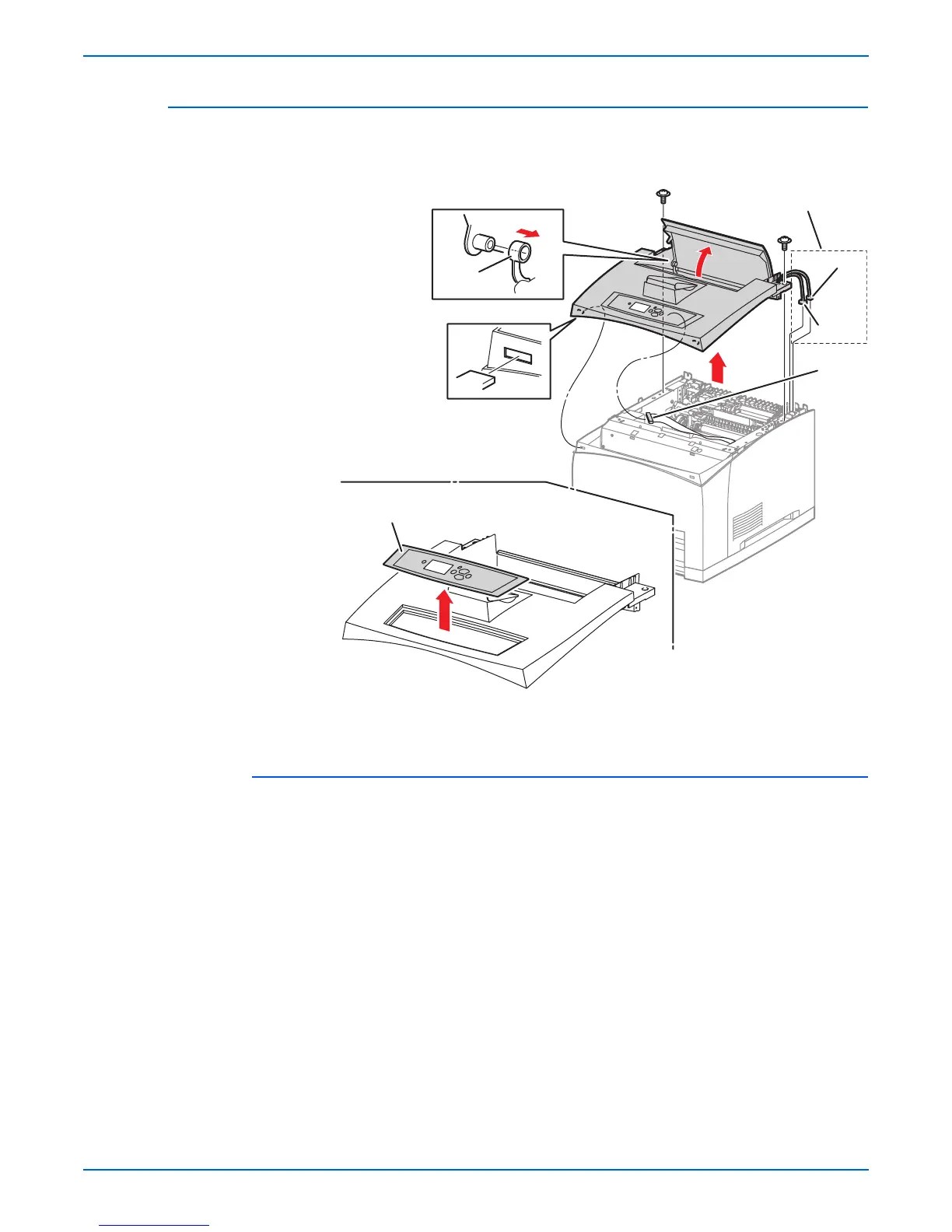
Top Cover Assembly, Control Panel
(PL1.1.7) (PL1.1.1)
Procedure:
o
e
The control panel can be removed without removing the top cover
assembly by prying up carefully on the right edge of the control panel and
disconnecting the harness.
1. Remove the print cartridge.
2. Remove the paper exit assembly (page 8-49).
3. P4500: Disconnect the connectors (P/J144 and P/J411) of the interlock
switch assembly from the frame connectors.
Note
The frame connectors referred to in step 3 are present only on the
Phaser 4500.
4. Remove the two screws (flanged, 8 mm) that secure the top cover
assembly to the printer.
1.Link lever 2.Control panel
s4510-060
P4500 Only
1
P/J411
P/J144
810
2

 Loading...


