8-82 Phaser 4500/4510 Service Manual
FRU Disassembly
Replacement Notes:
■ When installing the grounding plate, be sure to install the tip of the
grounding plate under the left cover plate.
■ Ensure all four hooks on the left cover plate are properly engaged by
pressing down on each while sliding it toward the front.
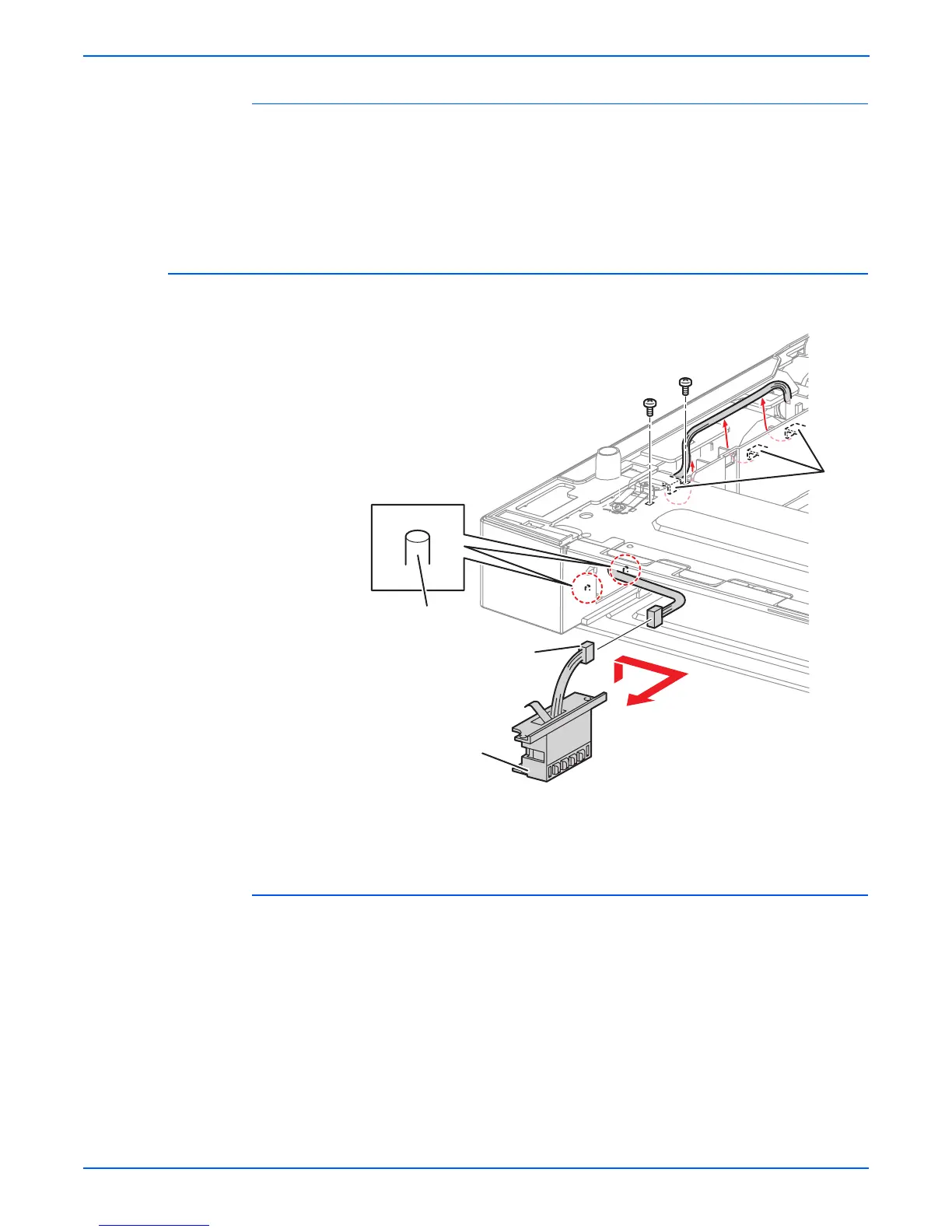
Option Paper Size Switch Assembly
(PL20.1.18)
Procedure:
1. Remove the two 8 mm tapping screws that attach the option paper size
switch assembly to the 550 left cover frame. These screws are accessed
through square cutouts in the metal frame on the top of the feeder.
2. Shift the option paper size switch assembly in the direction of the arrow to
release the bosses, and remove it from the 550 left cover frame. If
necessary, release the feeder size 1 assembly harness from the hooks of
the 550 left cover frame to get enough slack in the harness to make the
connector accessible.
3. Disconnect the connector (P/J802) of the feeder size 1 assembly harness
from the connector of the option paper size switch assembly.
1.Hooks 3.Bosses
2.Option paper size switch assembly
s4500-155
1
2
P/J802
3
 Loading...


