Phaser 4500/4510 Service Manual 8-49
FRU Disassembly
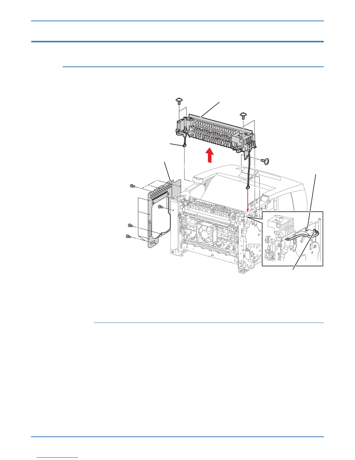
Print Engine: Paper Exit
Paper Exit Assembly
(PL10.1.2)
Procedure:
1. Remove the paper exit cover (page 8-4) or stacker (page 8-111) if
installed.
2. Remove the right cover (page 8-7
3. Remove the left cover (page 8-8).
4. Remove the image processor shield assembly (page 8-70).
5. Unplug J29 (the exit sensor harness assembly — gray wire) from P29 on
the HVPS/engine logic board, and release the harness from the two cable
restraints.
6. Unplug J103 (the exit motor assembly) from P103 on the exit motor
PWBA and carefully release the harness from the retainers on the gear
assembly housing.
1.Image processor shield assembly 3.Exit motor PWBA
2.Paper exit assembly
1
2
J29
s4500-128
3
J103
 Loading...


