Phaser 4500/4510 Service Manual 10-25
Wiring Diagrams
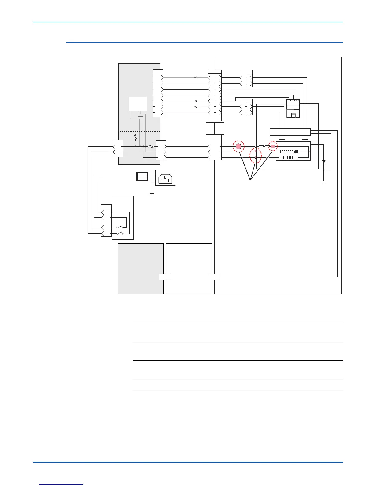
Fuser Assembly, Power Switch
Signal
line name
Description
/EXIT Signal from Exit Sensor. This signal goes Low when the flag moves out
of the sensor.
STS Temperature monitor signal (analog signal) from Temperature Sensor
(Thermistor). It detects the temperature on the surface of heat roller.
PRB Output from HVPS which applies a high voltage to pressure roller.
P/J46
2
1
1
2
P/J4249
3
1
2
3
4
5
6
7
1
2
3
4
5
6
7
1
6
5
4
3
2
1
7
P/J4647
STS 2
LVPS
LG
LG
LG
/ EXIT
STS 1
LINE
LINE
(Secondary)
NEUT
NEUT
NEUT
Pullup 3.3V
2
1
1
2
P/J4248
AC Connector
HVPS/
Engine Logic
PWBA
R. Print Cartridge
Guide
AC Harness
Fuser
Harness
Heater
Control
HVPS
TS
Fuser
FG
TS
Heat Roller
A4 Long
A4 Short
J1
J2
Pressure Roller
123
Exit
Sensor
FG
P/J480
3
1
P/J48
3
5
1
2
4
Power
Switch
P/J47
T1
2
1
3
PRB
(Primary)
Core
(Secondary)
(Primary)
s4510-236
P/J4247
P4500 Only
 Loading...


