Phaser 4500/4510 Service Manual 8-75
FRU Disassembly
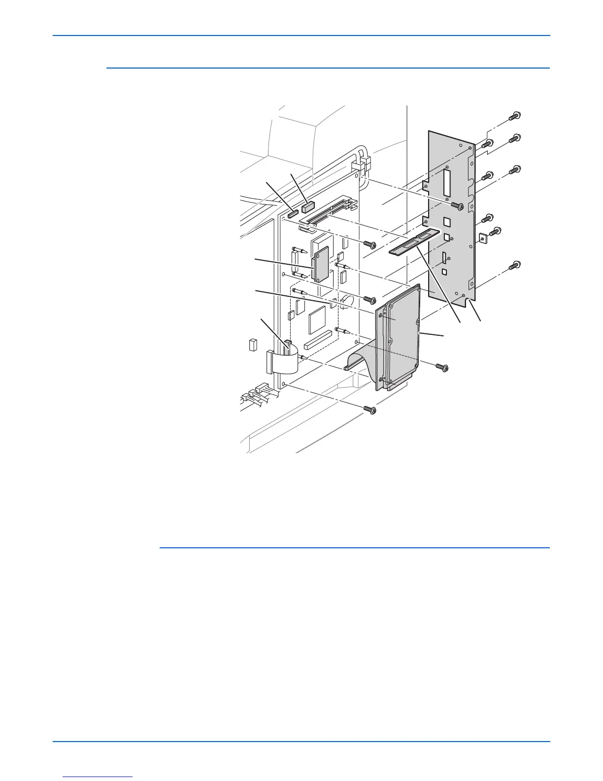
Image Processor (I/P) Board
(PL 12.1.13)
Procedure:
Caution
Observe electrostatic precautions when handling the I/P board and its
components.
Do not attempt to slide the I/P board out from the rear of the printer due to
the potential for damage to the capacitors along the bottom of the board.
1. Remove the right cover (page 8-7).
2. Remove the image processor shield assembly (page 8-70).
3. Unplug the ribbon cable from J800 (the connector to the HVPS/engine
logic board). Be sure to note the orientation of the blue stripe on the
ribbon.
1.Memory DIMMs 4.NVRAM (U660)
2.Flash memory (optional) 5.Rear panel
3.Hard disk drive (optional)
s4500-255
3
1
2
4
J110
J130
J800
5
P4500
 Loading...


