Phaser 4500/4510 Service Manual 8-39
FRU Disassembly
6. If a phillips screwdriver with a long shaft (min. 6.5 in (16.5 cm)) is
available, skip this step. Otherwise, remove the eight 6 mm machine
screws attaching the front tie plate to the frame, and remove the front tie
plate.
7. Release the cable clamp(s) from the front tie plate.
Caution
The printed circuit board on the laser unit assembly is fragile. Support
the circuit board to prevent it from flexing and possibly cracking when
unplugging the connectors in the following step.
Note
Do not touch the glass laser window strip with finger tips or anything
that could leave deposits.
8. Unplug the harness connector at P/J 131, and the three connectors,
P/J140, P/J160, and P/J170, from the laser unit circuit board.
9. Remove the four screws (flanged, 8 mm) that attach the laser unit
assembly to the frame.
10. Lift the laser unit assembly out of the printer frame.
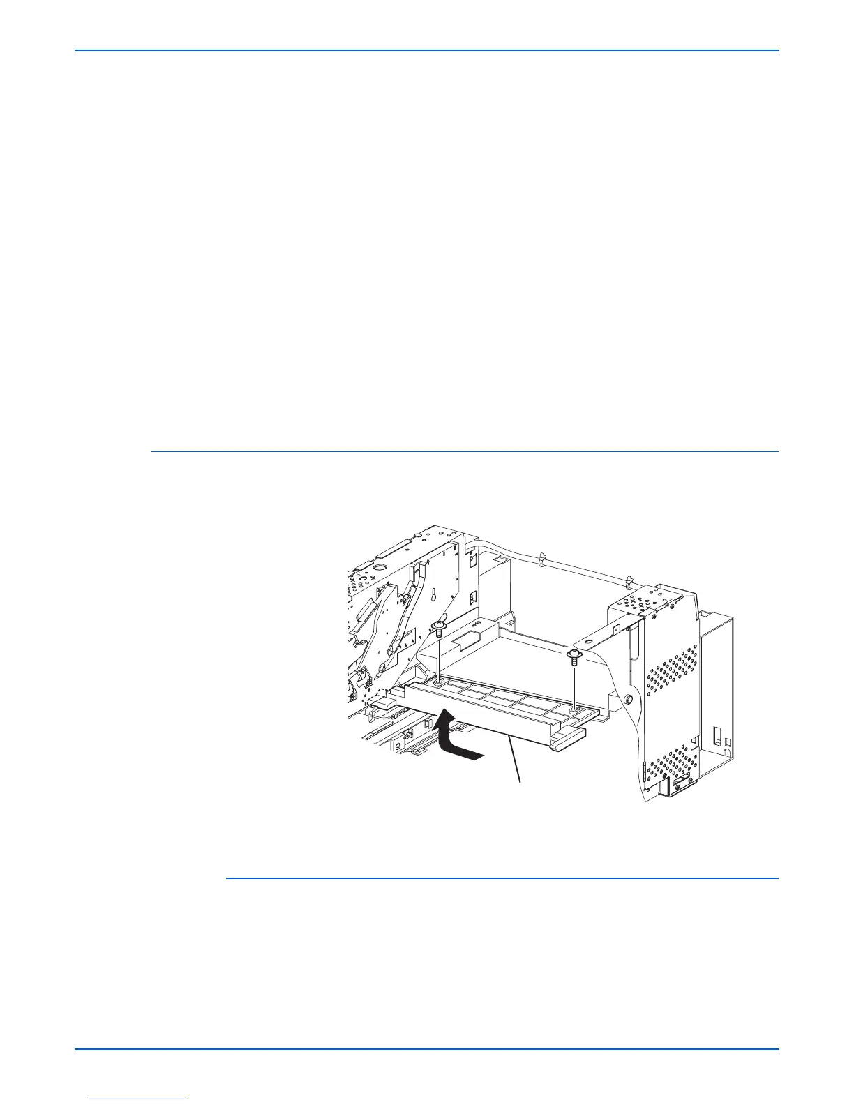
Laser Unit Shield Plate
(PL8.1.3)
Procedure:
1. Remove the laser unit assembly (page 8-38).
2. Remove the two screws (flanged, 8 mm) that attach the laser unit shield
plate to the frame.
3. Lift the laser unit shield plate out of the frame as indicated by the arrow.
1.Laser unit shield plate
1
s4500-114

 Loading...


