Phaser 4500/4510 Service Manual 10-17
Wiring Diagrams
Notations Used in Wiring Diagrams
The symbols in the interconnection wiring diagram are described below. Note
that the description of general symbols is omitted.
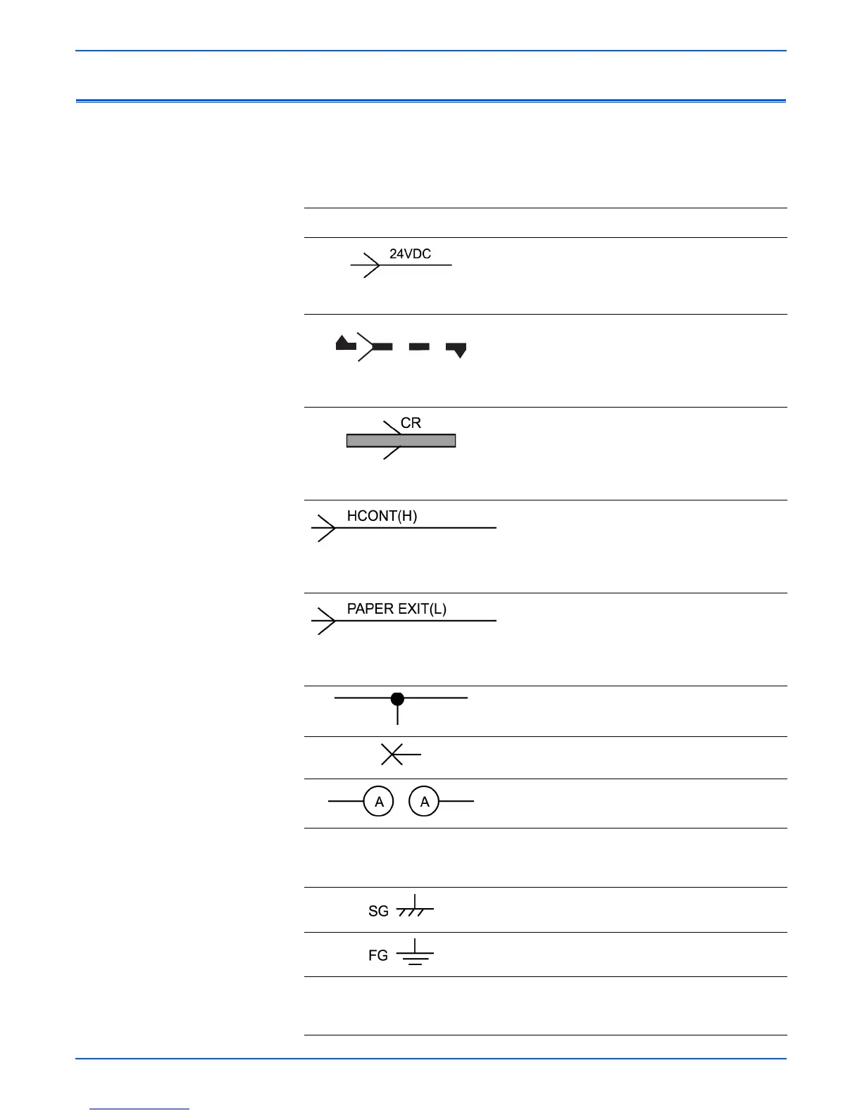
Symbol Description
Represents an interconnection between parts
using wiring harness or wire, and indicates its
signal name/contents. The arrow “>” or “<” on the
line represents the direction of signal flow.
Represents an interconnection between parts
using wiring harness or wire, which differs
according to the specifications, and indicates its
signal name/contents. The arrow “>” or “<” on the
line represents the direction of signal flow.
Represents a connection between parts using a
conductive member such as a plate spring, and
indicates its signal name/contents. The arrow “>”
or “<” on the line represents the direction of signal
flow.
Represents a function and a logical value (High
(H) or Low (L)) of a signal when the function is
activated. The voltage indicates a value when the
signal is High. The arrow indicates the direction of
signal flow.
Represents a function and a logical value (High
(H) or Low (L)) of a signal when the function is in
a detectable state. The voltage indicates a value
when the signal is High. The arrow indicates the
direction of signal flow.
Represents a connection between lead wires.
Represents a connection between parts by
tightening of a screw.
Represents a connection between “A” and “A”.
24 VDC
The DC voltage indicates an approximate value
measured when the negative side is connected to
a signal ground (SG).
Indicates a signal ground (SG).
Indicates a frame ground (FG).
RTN
Indicates a return.
24VDC
 Loading...


