8-12 Phaser 4500/4510 Service Manual
FRU Disassembly
Interlock Switch Assembly (P4500 only)
(PL1.1.11)
Procedure:
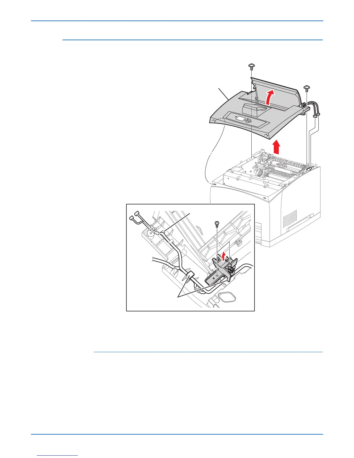
1. Remove the top cover assembly.
Note
The interlock switch assembly is attached to the underside of the top
cover assembly on the right hand side near the top cover opening.
2. Remove the two 8 mm tapping screws that attach the interlock switch
assembly.
3. Lift the interlock switch assembly from the top cover assembly, release the
harnesses from the cable restraints, and draw the interlock switch
harness out of the hole in the top cover assembly.
1.Top cover assembly 3.Cable Clamps
2. Hole
s4500-062
1
3
2

 Loading...


