8-76 Phaser 4500/4510 Service Manual
FRU Disassembly
4. Unplug the cables at J110 and J130 (P4500) or J120 and 200 (P4510)
near the top of the board.
5. Remove the four screws that attach the rear panel to the printer frame.
6. Remove the five 6 mm machine screws that mount the board and lift out
the board with the rear panel attached.
P4510: Do not slide out from the rear. Tilt the top of the board out of the
printer, then lift out.
Note
The remaining steps cover the removal of parts attached to the I/P
board that must be transferred when installing a new I/P board.
7. Remove the memory DIMM(s).
8. Remove the optional flash memory (if present) from J850.
9. Remove the optional hard drive (if present).
P4500: Squeeze the tips of the standoffs to release the drive circuit
board, then unplug the ribbon cable.
P4510: Squeeze the tips of the standoffs to release the drive circuit
board, then squeeze the tips of the standoffs to release the plug board
and unplug from the I/P board.
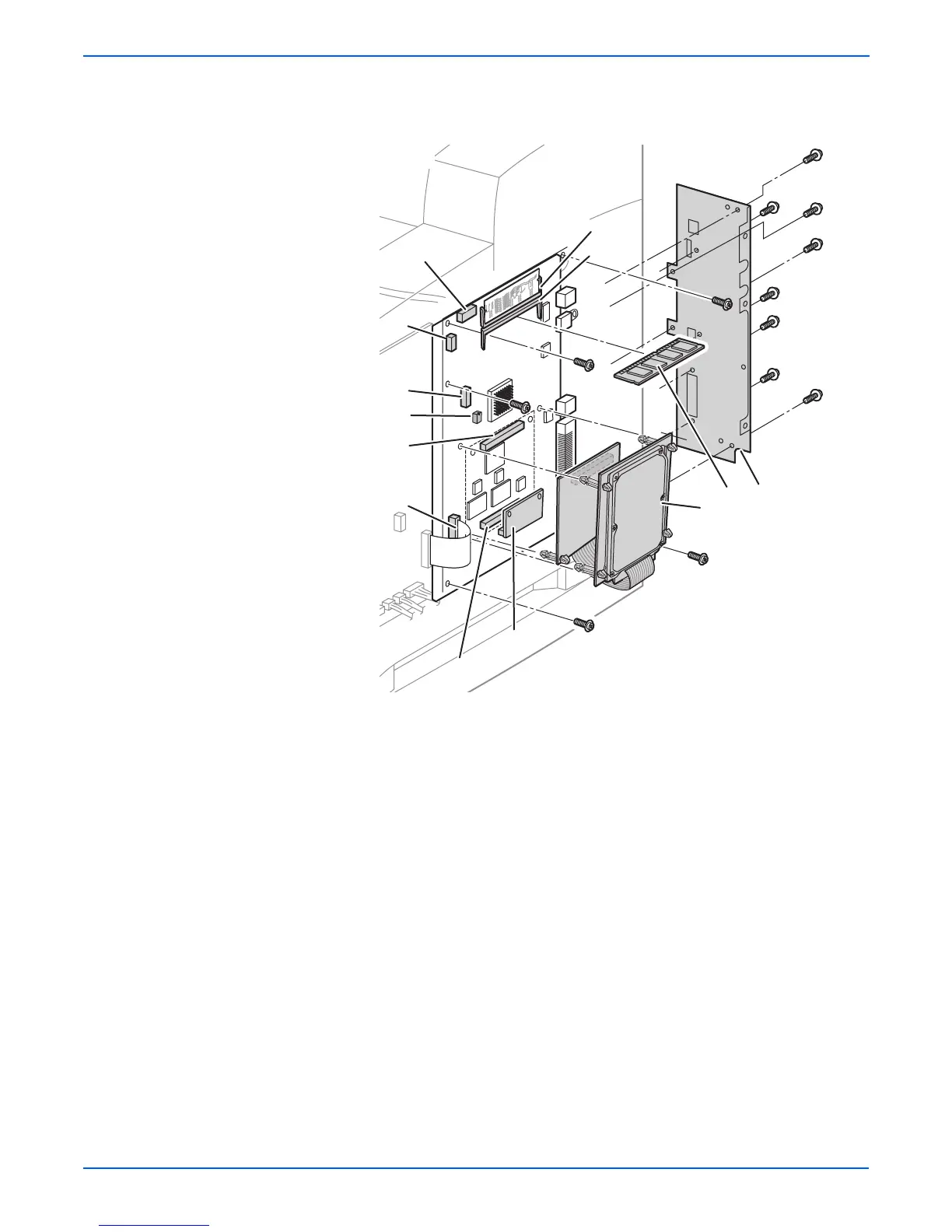
1.Memory DIMMs 4.NVRAM (U520) - Notch at top
2.Flash memory (optional) J850 5.Rear panel
3. Hard disk drive (optional) J650
J410
J850
J650
J340
J240
P4510
s4510-255
3
1
2
J800
5
J120
J200
4
 Loading...


