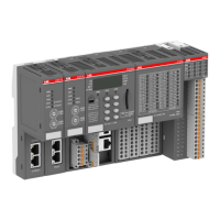
Table 74: Assignment of the other terminals:
Terminals Signal Description
1.0 to 1.7 I0 to I7 Input signals of the 8 digital
inputs
1.8 to 4.8 UP Process supply voltage +24 V
DC
1.9 to 4.9 ZP Reference potential for the 8
digital inputs and the process
supply voltage
2.0 R0 Common contact of the first
relay output
3.0 NO 0 Normally-open contact of the
first relay output
4.0 NC 0 Normally-closed contact of the
first relay output
2.1 R1 Common contact of the
second relay output
3.1 NO 1 Normally-open contact of the
second relay output
4.1 NC 1 Normally-closed contact of the
second relay output
: : :
2.7 R7 Common contact of the eighth
relay output
3.7 NO 7 Normally-open contact of the
eighth relay output
4.7 NC 7 Normally-closed contact of the
eighth relay output
The internal power supply voltage for the module's circuitry is carried out via the I/O bus
(provided by a communication interface module or a CPU). Thus, the current consumption from
24 V DC power supply at the terminals L+/UP and M/ZP of the CPU/communication interface
module increases by 2 mA per DX522.
The external power supply connection is carried out via the UP (+24 V DC) and the ZP (0 V DC)
terminals.
I/O modules > Digital I/O modules
2022/01/313ADR010278, 3, en_US330

 Loading...