1.0
1.1
1.2
1.3
1.4
1.5
1.6
1.7
1.8
1.9
CANopen in
CANopen out
1.0
1.1
1.2
1.3
1.4
1.5
1.6
1.7
1.8
1.9
CANopen end
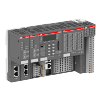
In the case of TU517/TU518, the terminating resistors are not located inside
the TU but inside the communication interface module CI581-CN. Hence, when
removing the device from the TU, the bus terminating resistors are no longer
connected to the bus. The bus itself will not be disconnected if a device is
removed.
The grounding of the shield should take place at the switchgear cabinet.
Please refer to the AC500 System-Data
Ä
Chapter 2.6.1 “System data AC500”
on page 971.
Communication interface modules (S500) > CANopen
2022/01/31 3ADR010278, 3, en_US 663

 Loading...