SYSTem Subsystem 12
N1911A/1912A P-Series Power Meters Programming Guide 559
1
The Range setting in Table 12-48 is only applicable for E-Series power sensor and N8480 Series
power sensor (excluding Option CFT).
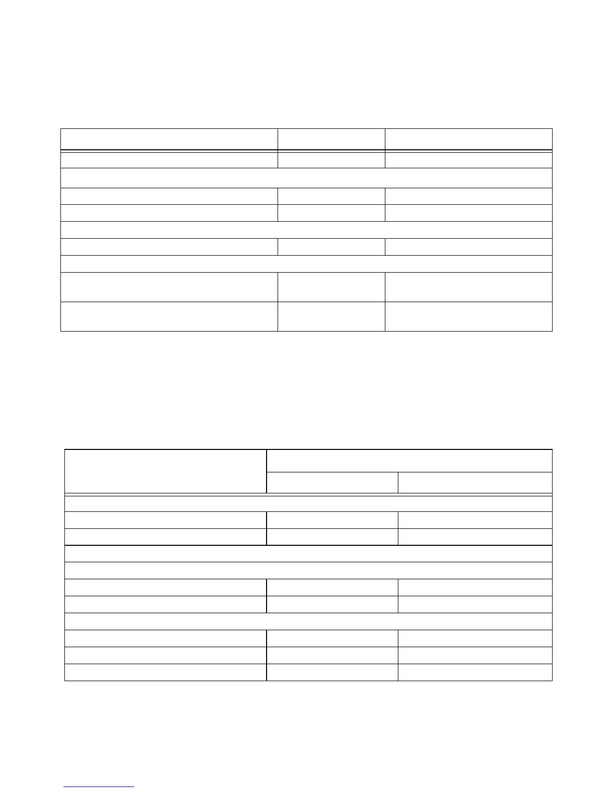
Tab le 12-49 RADAR: Power Meter Presets: Window/Measurement Settings
TRIG[:SEQ]:HOLD MIN Trigger holdoff
Range
1
[SENS[1]]|SENS2:POW:AC:RANG:AUTO OFF Auto range off
[SENS[1]]|SENS2:POW:AC:RANG UPPER Range set to upper
Step detection
[SENS[1]]|SENS2:AVER:SDET 0 Step detection disabled
Trace setup
[SENS[1]]|SENS2:TRAC:OFFS
:TIME <numeric_value>
–250 ns Delay between delayed trigger point
and the start of the trace
[SENS[1]]|SENS2:TRAC:TIME
<numeric_value>
1.5 µs Length of the trace
Command Setting Comments
Function Setting
Single Channel Dual Channel
Display setup
Upper window Channel A trace See Table 12-50
Lower window Dual numeric Dual numeric
Window/measurement setup
Upper window/upper measurement (UU)
Feed Gate 1 Channel A See Table 12-50
Measurement Pk-to-Avg See Table 12-50
Upper window/lower measurement (UL)
Feed 1 Gate 2 Channel A - Avg See Table 12-50
Feed 2 See Table 12-50
Measurement Feed 1/ Feed 2 See Table 12-50

 Loading...


