12 SYSTem Subsystem
596 N1911A/1912A P-Series Power Meters Programming Guide
1
The Range setting in Ta b l e 1 2 - 8 1 is only applicable for E-Series power sensor and N8480 Series
power sensor (excluding Option CFT).
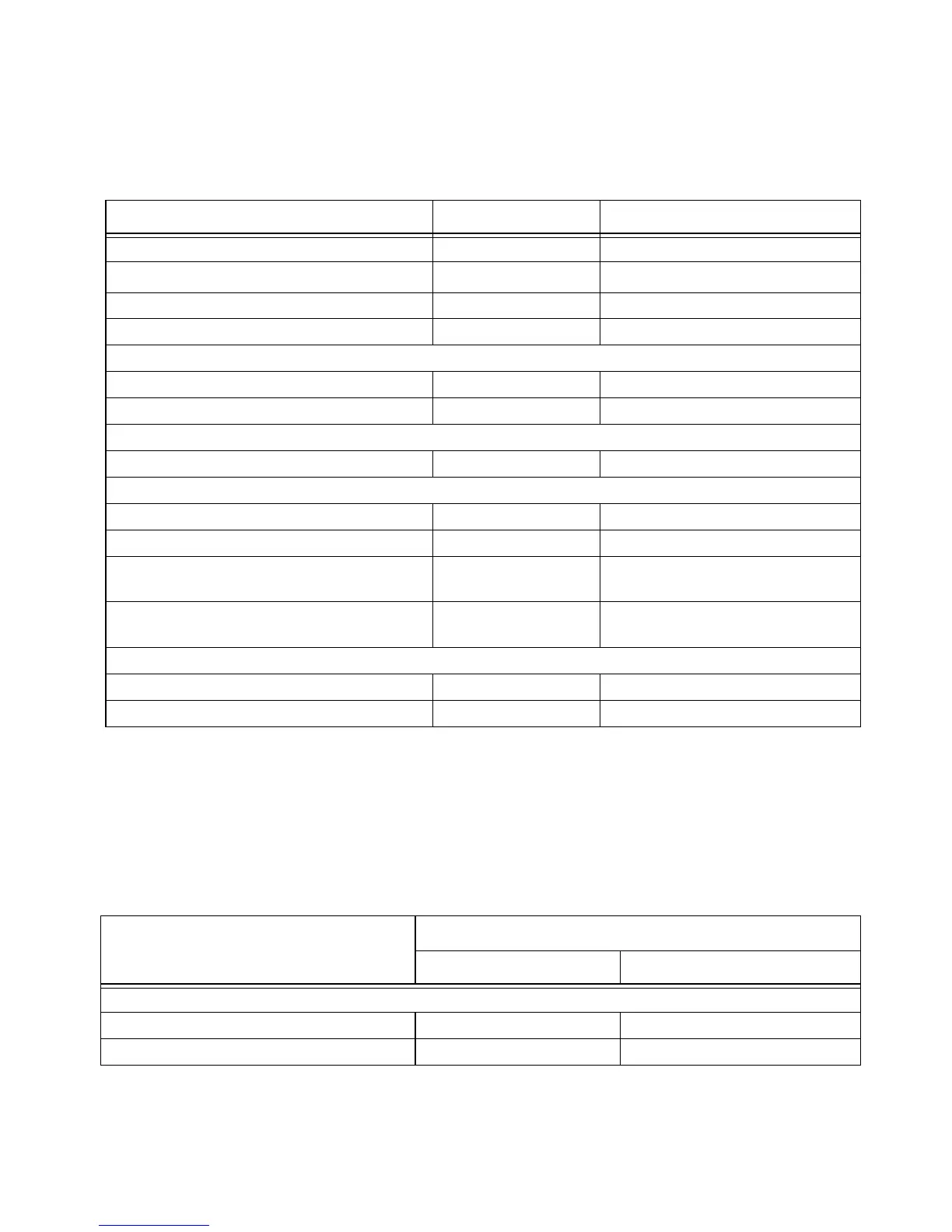
Tab le 12-82 DME-PRT: Power Meter Presets: Window/Measurement Settings
TRIG[:SEQ]:HOLD 50 µs Trigger holdoff
Range
1
[SENS[1]]|SENS2:POW:AC:RANG:AUTO OFF Auto range off
[SENS[1]]|SENS2:POW:AC:RANG UPPER Range set to upper
Video averaging setup
[SENS[1]]|SENS2:AVER2[:STAT] 1 Video averaging is enabled
[SENS[1]]|SENS2:AVER2:COUN 32 Length of video filter
Step detection
[SENSe[1]]|SENS2:AVER:SDET 0 Step detection disabled
Trace setup
SENS[1]|2:TRAC:LIM:UPP +20 dBm Maximum power
SENS[1]|2:TRAC:LIM:LOW -30 dBm Minimum power
[SENS[1]]|SENS2:TRAC:OFFS
:TIME <numeric_value>
-2 µs Delay between delayed trigger point
and the start of the trace
[SENS[1]]|SENS2:TRAC:TIME
<numeric_value>
5 µs Length of the trace
Reference level setup
TRAC[1]|2:DEF:TRAN:REF 0.25%, 9% Transition reference levels
TRAC[1]|2:DEF:DUR:REF 25% Pulse duration reference level
Command Setting Comments
Function Setting
Single Channel Dual Channel
Display setup
Upper window Channel A trace See Table 12-83
Lower window Dual numeric Dual numeric

 Loading...


