12 SYSTem Subsystem
534 N1911A/1912A P-Series Power Meters Programming Guide
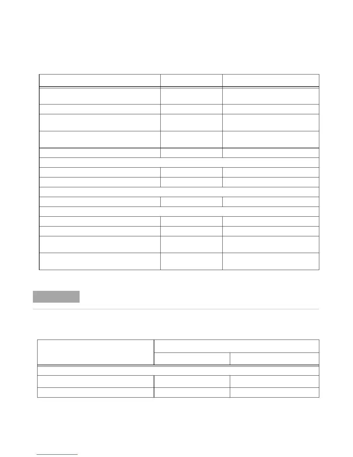
Tab le 12-28GSM900: Power Meter Presets: Window/Measurement Settings
TRIG[:SEQ]:LEV:AUTO OFF Disable automatic setting of the trigger
level
TRIG[:SEQ]:LEV –15 dBm Power level
TRIG[:SEQ]:SLOP POS Trigger event recognized on the rising
edge of a signal
TRIG[:SEQ]:DEL 20 µs Delay between recognition of trigger
event and start of a measurement
TRIG[:SEQ]:HOLD 4275 µs Trigger holdoff
Range
[SENS[1]]|SENS2:POW:AC:RANG:AUTO OFF Auto range off
[sens[1]]|SENS2:POWER:AC:RANG UPPER Range set to upper
Step detection
[SENSe[1]]|SENS2:AVER:SDET 1 Step detection enabled
Trace setup
SENSe[1]|2:TRAC:LIM:UPP +20 dBm Maximum power
SENSe[1]|2:TRAC:LIM:LOW –35 dBm Minimum power
[SENS[1]]|SENS2:TRAC:OFFS
:TIME <numeric_value>
–40 µs Delay between delayed trigger point
and the start of the trace
[SENS[1]]|SENS2:TRAC:TIME
<numeric_value>
700 µs Length of the trace
Command Setting Comments
The Range setting in Table 12-27 is only applicable for E-Series power sensor and N8480
Series power sensor (excluding Option CFT)
.
Function Setting
Single Channel Dual Channel
Display setup
Upper window Channel A trace
Primary channel
*
trace
Lower window LU single numeric See Table 12-29

 Loading...


