A Calibration Factor Block Layout
A-764 N1911A/1912A P-Series Power Meters Programming Guide
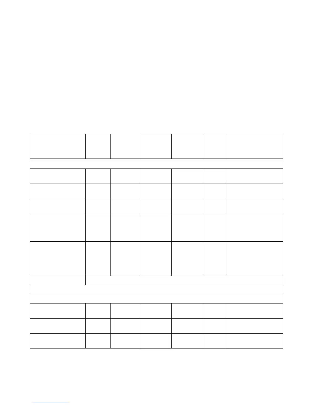
Calibration Factor Block Layout
The following tables provide information on the calibration factor block
layout for E4410 Series, E9300 Serie, E9320 Series and N8480 Series
sensors (excluding Option CFT). The information relates to service
commands is described in Chapter 15.
Tab le A-9 6 Calibration Factor Block Layout: E4410 Series Sensors
E4410 Series
Sensors: Calibration
Factor Block Layout
No.
Bytes
Contents Data
Format
Data
Range
Units Notes
Header:
Power, low 2 - 7.8 (signed) –127.9 to
+127.9
dBm Power for low power
flatness.
Power, high 2 - 7.8 (signed) –127.9 to
+127.9
dBm Power for high power
flatness.
Number of frequency
points
2 - 16 bit
integer
-None
Bytes per frequency
point
1 - - - None Number of bytes in cal
factor value at each
frequency and power
level.
Frequency LSB weight 2 1000 - Hertz Fhbp (Freq. Hz per bit).
1 KHz per bit for the cal
factor: 1 KHz x 2^32 =
4.3E+12 = 4300 GHz
range
Header Total: 9
Cal Factor Table:
Frequency (point ‘0’) 4 - 32 bit fixed 0 to Fhpb*
(2^32)
None Fhpb = Freq Hz per bit
Cal factor (low power)
1
2 - 2.14 0.25 to 3 None Power (in watts) is
divided by this value.
Cal factor (high power)
1
2 - 2.14 0.25 to 3 None Power (in watts) is
divided by this value.

 Loading...


